
Performance Specs: %OS, Ts, Tr, Tp, Ess (Steady-State Error)
Learn how %OS, Ts, Tr, Tp, and Ess define embedded control loop behavior, and how to trade them off against stability and gain margin.
Contents & prerequisites
Why Performance Specifications Matter in Embedded Control
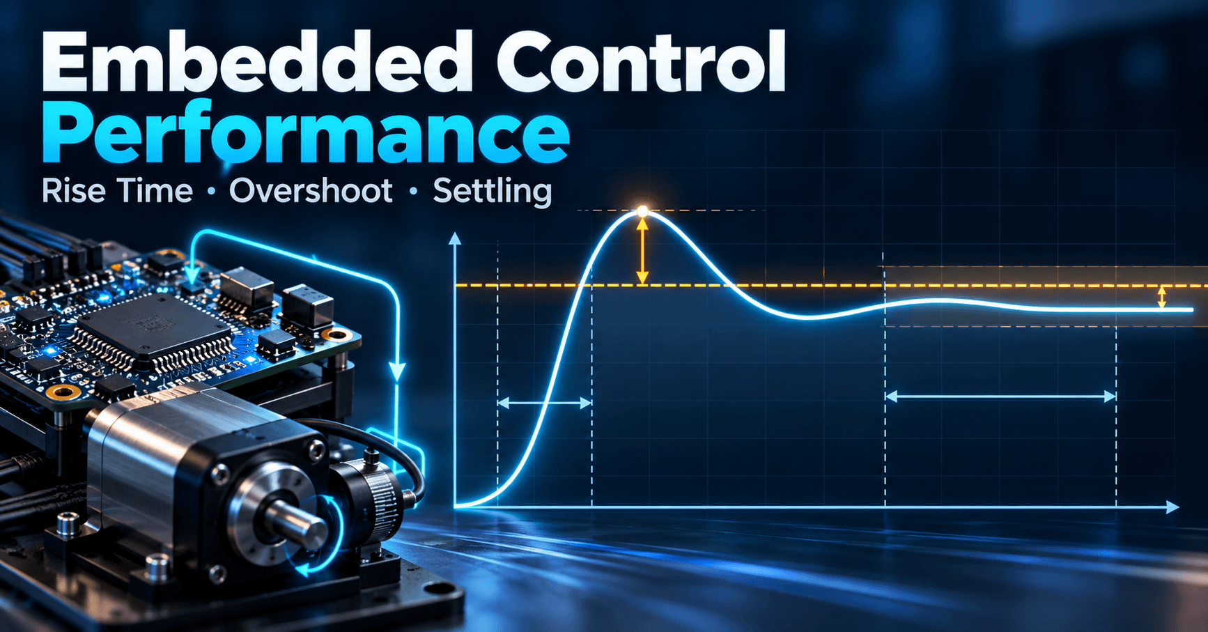
Every control loop running on a microcontroller — a motor position servo, a thermal regulator, a buck converter's voltage loop — ultimately gets judged by the same handful of numbers. How fast does it respond? Does it overshoot the target and ring before settling? Does it converge to the right value at all, or does it park a few percent off? These questions are answered by five specifications: rise time (Tr), peak time (Tp), percent overshoot (%OS), settling time (Ts), and steady-state error (Ess). They are the vocabulary a requirements document uses to talk to a control engineer, and the numbers a control engineer uses to talk back to firmware, mechanical, and systems teams.
The role of transient and steady-state metrics in system design
Transient specs (Tr, Tp, %OS, Ts) describe the system's behavior during the first few time constants after a disturbance or setpoint change. Steady-state error describes what's left over after everything has settled. Both matter, but they stress different parts of the design: transient response is dominated by closed-loop pole locations and damping, while steady-state accuracy is dominated by loop gain and system type at DC.
How specifications drive hardware and software trade-offs
A 2% settling-time requirement of 50 ms on a current loop might force a higher PWM switching frequency, a faster ADC, or a tighter interrupt period just so the discrete controller can even realize the required bandwidth. A tight %OS requirement on a stepper or servo axis may force you to accept a slower rise time, because the two are physically coupled through damping ratio. These aren't abstract trade-offs — they show up as sensor sample-rate budgets, actuator saturation limits, and gain-scheduling tables.
Real-world consequences of poor performance metrics
An underdamped thermal loop that overshoots its setpoint can trip a safety threshold. A motion system with excessive settling time blows a tact-time budget on a production line. A pressure regulator with nonzero steady-state error under a ramp-type demand will drift the actual process variable away from target continuously. These are not "tuning polish" issues; they are functional failures that trace directly back to a sloppy handling of these five specs.
Transient Response Specifications
Rise Time (Tr): Definition and measurement conventions
Rise time is the time for the response to go from 10% to 90% of its final value for overdamped or critically damped systems, or 0% to 100% for underdamped second-order systems. Firmware engineers should always state which convention a test report uses — 10–90% vs 0–100% rise time differ enough to cause false "spec miss" arguments between teams when nobody checks the definition.
Peak Time (Tp): When and where the first overshoot occurs
Peak time is the time at which the response hits its first (and largest) overshoot, and it exists only for underdamped systems (damping ratio ζ < 1). For a standard second-order system with natural frequency ωn and damping ratio ζ, Tp = π / (ωn√(1−ζ²)). Tp and %OS are not the same measurement and answering "how fast" and "how much" separately matters: a system can have a late peak time but a small overshoot (well damped, slow), or an early peak time with a large overshoot (fast but underdamped and potentially stressing mechanical linkages or driving current limiters). An embedded engineer sizing a current limit or a mechanical stop needs %OS; one sizing a watchdog timeout for "has the loop started responding" needs Tr and Tp.
Percent Overshoot (%OS): Quantifying overshoot relative to steady-state
%OS = (peak value − final value) / final value × 100%. For the standard second-order model, %OS = exp(−ζπ/√(1−ζ²)) × 100%. This formula is the one you invert during design: pick an allowable %OS, solve for the minimum ζ, and that ζ becomes a hard constraint on your controller's pole placement.
Settling Time (Ts): Tolerance bands and practical thresholds
Settling time is the time for the response to stay within a tolerance band (commonly ±2%, sometimes ±5%) of final value. The approximation Ts ≈ 4/(ζωn) for 2% band (or 3/(ζωn) for 5%) comes directly from the envelope of the decaying exponential e^(−ζωnt). Always state the tolerance band in a spec sheet — "Ts = 200 ms" is meaningless without it.
Steady-State Error (Ess): Accuracy at Rest
What steady-state error represents and why it matters
Ess is the difference between commanded input and actual output after transients die out. It is computed with the Final Value Theorem: lim(t→∞) y(t) = lim(s→0) sY(s), applied to the error signal E(s) = R(s)/(1+L(s)) for unity feedback, giving ess = lim(s→0) sR(s)/(1+L(s)).
Error constants for step, ramp, and parabolic inputs
For a unity-feedback loop with open-loop transfer function L(s), define:
- Kp = lim(s→0) L(s) → ess(step) = 1/(1+Kp)
- Kv = lim(s→0) sL(s) → ess(ramp) = 1/Kv
- Ka = lim(s→0) s²L(s) → ess(parabola) = 1/Ka
Worked example: L(s) = 10/(s(s+5)). This is Type 1 (one free integrator). Kp = ∞ → ess(step) = 0. Kv = lim s·10/(s(s+5)) = 10/5 = 2 → ess(ramp) = 1/2 = 0.5 (50% of ramp slope, in output units). Ka = 0 → ess(parabola) = ∞.
System type and its relationship to Ess
System type is the number of pure integrators (poles at s=0) in L(s). Type 0 systems have finite Ess for a step and infinite Ess for a ramp. Type 1 drives step error to zero but has finite ramp error. Type 2 drives both to zero but is rare in practice because the extra integrator makes stabilization much harder.
Trade-off between Ess reduction and stability margins
Adding integral gain (or an extra integrator) reduces Ess but adds phase lag near crossover, eating into your Gain Margin: GM = -20log|L(jωpc)| > 6 dB Desired. In practice, tune integral gain as high as the margin budget allows, then accept the residual ramp-following error, or add a feedforward term instead of pushing the integrator harder.
Extracting Specs from the Closed-Loop Response
Reading %OS and Ts directly from step response plots
On a logged step response: find the peak value and the final (steady-state) value to compute %OS; find where the response permanently enters the ±2% band around final value to get Ts; find the 10–90% crossing times for Tr. Most lab tooling (scope cursors, MATLAB's stepinfo()) automates this, but knowing the manual method lets you sanity-check firmware-logged data from a UART trace.
Using impulse and ramp responses to diagnose Ess
A step response only reveals step-error. To check ramp-following behavior, command an actual ramp setpoint and watch the steady lag between commanded and actual trajectories — that lag, once constant, is your ramp Ess.
Interpreting overshoot when there is no clear peak
Overdamped or critically damped systems (ζ ≥ 1) show no overshoot at all, so %OS = 0 and Tp is undefined. If a logged response looks monotonic but slow, check Tr and Ts instead of hunting for a peak that doesn't exist.
Impact of dominant poles on observable transient behavior
Real embedded plants are rarely clean second-order systems. The Dominant Poles Approximation for Higher-Order Systems lets you treat the closest-to-the-imaginary-axis pole pair as the one setting Tr, Tp, %OS, and Ts, provided other poles/zeros are at least 5x farther left. Validate this assumption against your actual Characteristic Equation and Closed-Loop Poles before trusting second-order formulas.
Performance–Stability Trade-offs
How faster rise time and lower settling time reduce stability margins
Faster Tr and Ts require higher loop bandwidth (larger ωn), which pushes crossover frequency higher — right where parasitic poles, sensor delay, and sampling zero-order-hold phase lag start eating your margin.
Relationship between %OS specifications and gain margin requirements
Lower allowed %OS requires higher ζ, which generally correlates with a larger phase margin. A common embedded rule of thumb is PM (degrees) ≈ 100ζ for ζ < 0.7 — useful for a first-pass target, not a substitute for simulation.
Damping ratio and natural frequency as design intermediates
ζ and ωn are the bridge between the frequency-domain stability world and the time-domain spec world. Design in (ζ, ωn) space, then verify both %OS/Ts and gain/phase margin before committing gains to flash.
Balancing robustness against performance demands
Treat %OS and Ts targets as a budget, not a minimum to be beaten by as much as possible — margin spent on performance is margin unavailable for component tolerance, temperature drift, and aging.
Practical Design Workflow
Translating application requirements into %OS, Ts, and Ess targets
Start from the mechanical/thermal/electrical tolerance of the end application (e.g., "valve must not overshoot pressure by more than 3%, must settle within 300 ms, must hold setpoint within 0.5% under constant flow demand") and convert directly into ζ, ωn, and system-type requirements.
Controller gain tuning to meet multiple specifications simultaneously
Because %OS constrains ζ and Ts constrains ζωn, pick the pole location first, then check that the resulting loop gain gives acceptable Ess; iterate with integral action if Ess fails.
Testing and validation against specification thresholds
Validate with step, ramp, and (if relevant) parabolic test inputs on the actual hardware — simulation models never capture every real-world nonlinearity (PWM quantization, stiction, ADC noise).
Common pitfalls: over-constraining and under-specifying
Don't specify Tr, Tp, %OS, Ts, and Ess all at their tightest plausible values simultaneously — second-order dynamics couple them, and an over-constrained spec set may be mathematically infeasible. Conversely, don't leave Ess unspecified for ramp-tracking applications; "it looked fine on a step test" is a common and costly oversight.
Learning
Sign in to track your progress.
Evidence
Public projects engineers linked to Performance Specs: %OS, Ts, Tr, Tp, Ess (Steady-State Error).
No engineer has linked a project to this topic yet. Built something that proves it? Add the project and tag it with control-systems-performance-specs-os-ts-tr-tp-ess-steady-state-err — it then shows here and on your public profile.