
Time Synchronization: gPTP (IEEE 802.1AS) in Automotive
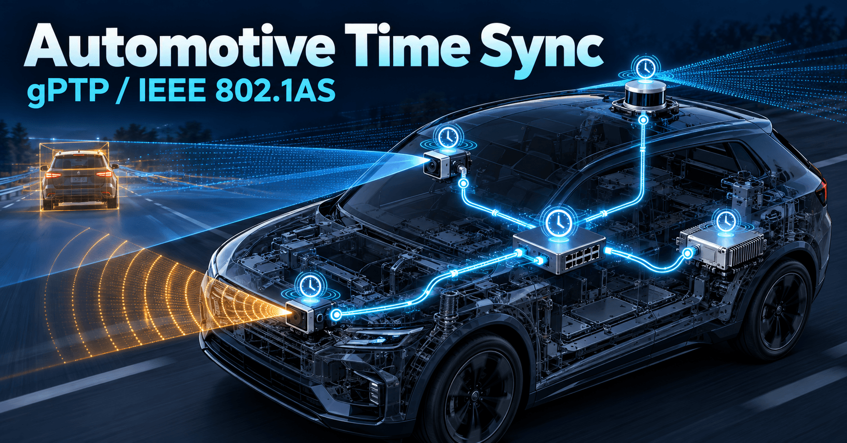
gPTP (IEEE 802.1AS) explains how automotive Ethernet ECUs reach microsecond time sync for ADAS, beyond CAN timing limits, with AUTOSAR integration.
Contents & prerequisites
Why Automotive Systems Need Precise Time Synchronization
Real-time constraints in ADAS and safety-critical functions
A forward radar, a camera ECU, and a lidar processor each generate object lists on independent clocks. The sensor fusion node that merges those lists needs to know, to within a few microseconds, when each measurement was actually taken — not when the packet arrived. At 120 km/h a vehicle covers roughly 3.3 cm per millisecond. A 1 ms timestamp error between camera and radar frames is enough to misplace a tracked object by several centimeters at the fusion stage, which is not acceptable when the output feeds an emergency braking decision. Timestamping accuracy is therefore not a convenience metric — it's an input to the safety case.
Multi-ECU coordination across Ethernet networks
Modern E/E architectures are consolidating dozens of CAN-attached ECUs behind zonal gateways connected by automotive Ethernet backbones running at 100BASE-T1, 1000BASE-T1, or higher. Sensor fusion, trajectory planning, and actuation now span multiple physically separate compute nodes instead of living inside one microcontroller. That distribution only works if every node agrees on "now." gPTP (IEEE 802.1AS) is the mechanism that gives every ECU on the Ethernet fabric a shared notion of time without requiring a GPS receiver at every node.
Determinism vs. traditional CAN timing limitations
CAN gives you reasonably predictable bus arbitration, but it has no native concept of a synchronized wall clock across nodes. Each ECU runs its own free-running oscillator, and any "time" information exchanged over CAN is really just a counter value carried in a message payload, subject to bus latency, arbitration delay, and software jitter at both ends. You can get millisecond-ish alignment with careful engineering, but CAN was never designed to characterize and remove propagation delay the way gPTP does. gPTP measures link delay explicitly, per port, and continuously compensates for it — something no CAN-based time distribution scheme does natively.
Regulatory and functional safety requirements
ISO 26262 doesn't mandate a specific synchronization protocol, but it does require that systematic and random timing faults affecting safety functions be identified and bounded. If your ASIL-D emergency-braking function depends on fused sensor data, your safety case needs a documented, bounded timing-error budget for that fusion — and gPTP's standardized offset and path-delay measurements give you numbers you can actually put in that budget, rather than "it's usually fine."
IEEE 802.1AS (gPTP) Protocol Fundamentals
Overview: Generalized Precision Time Protocol for automotive
gPTP is a profile of IEEE 1588 (PTP) standardized by IEEE 802.1AS, tailored for time-sensitive networking in bridged and automotive LANs. Compared to generic PTP, gPTP restricts itself to a single, simpler profile: it assumes a single spanning-tree-like time distribution hierarchy, mandates peer-to-peer delay measurement on every link, and drops features like end-to-end delay mechanism and arbitrary PTP domains that automotive networks don't need. The result is a lighter, more deterministic protocol suited to switched Ethernet with a known, fixed topology — which is exactly the automotive case, as opposed to the more heterogeneous networks PTP was designed for in telecom and industrial metrology.
Clock hierarchy: Grand Master, Boundary, and Ordinary Clocks
One node is elected Grand Master (GM) and becomes the time reference for the whole domain. Switches and gateways that sit between the GM and leaf ECUs act as Boundary Clocks (actually, in 802.1AS terms, Time-Aware Bridges), relaying corrected time from one port to the next while removing their own residence and link delay. Leaf ECUs are Ordinary Clocks — they synchronize to the upstream bridge but don't forward time further. This hierarchy mirrors the physical Ethernet topology, so timing accuracy depends directly on how many hops separate a given ECU from the GM.
Best Master Clock Algorithm (BMCA) and clock selection
BMCA is how the network decides, without manual configuration, which clock is the best candidate to be GM. Every node periodically sends Announce messages carrying a clockQuality dataset — clock class, accuracy, variance, and a configured priority1/priority2 pair. Each receiving node compares the advertised dataset against its own and against what it hears from other ports, deterministically ranking clocks by priority1, then clock class, then accuracy, then variance, then priority2, then clock identity as a tiebreaker. The node with the best dataset wins and all others converge their port states (master, slave, passive) around it. Because the comparison is a strict total order, every node in the domain reaches the same conclusion independently — that's what makes BMCA deterministic rather than requiring a central arbiter.
Message types: Announce, Sync, Follow_Up, and Delay_Req
- Announce — carries GM identity and quality data, drives BMCA.
- Sync — sent by the master, marks the instant of transmission; in the one-step variant the timestamp rides in the frame itself, in two-step it's sent separately.
- Follow_Up — carries the precise transmit timestamp of the preceding Sync when two-step timestamping is used, which is the common case in automotive MACs.
- Pdelay_Req / Pdelay_Resp / Pdelay_Resp_Follow_Up — the peer-delay exchange used to measure link propagation delay on every point-to-point link, independent of the Sync/Follow_Up flow.
gPTP over Automotive Ethernet (TSN Profile)
Integration with Time-Sensitive Networking (TSN)
gPTP is the timing backbone that other TSN standards build on. Scheduled traffic (802.1Qbv) needs every bridge to agree on absolute time to open and close gates for time-triggered frames in lockstep; without gPTP, a Qbv schedule is meaningless because each switch would be gating traffic against a different clock.
802.1Qcc stream reservation and scheduling
802.1Qcc defines how streams are configured and reserved — statically, via a centralized network configuration entity, or dynamically via enhanced MSRP. These reservations specify bandwidth and latency requirements per stream, but the guarantees they provide are only as good as the underlying time base; a reservation that assumes synchronized gate schedules across bridges depends on gPTP convergence having already happened and staying within its accuracy bound.
Deterministic Ethernet vs. standard switched networks
A standard switched Ethernet network gives you best-effort forwarding — queuing delay varies with instantaneous traffic load, and worst-case latency is hard to bound. TSN plus gPTP turns that into a deterministic fabric: time-aware shapers release time-critical frames in scheduled windows, and because all bridges share a common clock, the schedule is consistent network-wide. This is the same deterministic networking philosophy discussed in Industrial IoT (IIoT) vs. Consumer IoT Differences, where industrial fieldbuses traded raw throughput for predictability long before Ethernet caught up.
Port roles and path delay measurement
Each gPTP port is in one of several states — master, slave, passive, disabled — assigned by BMCA, and independently runs the peer delay mechanism to measure propagation delay on its link, typically every 1 second by default (tunable per implementation). This per-link measurement is what lets a multi-hop network maintain sub-microsecond accuracy even as frames cross several Time-Aware Bridges.
Clock Synchronization Mechanism and Accuracy
Offset correction: sync message propagation and processing delay
When a Sync/Follow_Up pair arrives, the receiving clock computes:
offset = t_receive_local - t_departure_master - meanLinkDelay - correctionField
t_departure_master comes from the Follow_Up timestamp, meanLinkDelay from the peer-delay exchange, and correctionField accumulates residence time corrections applied by each Time-Aware Bridge along the path. The slave clock servo then nudges its local time by this offset, typically using a proportional-integral filter rather than a step jump, to avoid discontinuities that would upset other time-dependent software.
Rate correction: frequency alignment between master and slave
Offset alone isn't enough — oscillators drift at different rates. gPTP tracks the ratio of elapsed master time to elapsed local time across successive Sync intervals and adjusts the local clock's frequency (rateRatio) to match the master's tick rate, not just its instantaneous value. This is what keeps two ECUs aligned between Sync messages rather than only at the moment a Sync arrives.
Achieving microsecond-level precision in automotive environments
Specific accuracy figures depend on your GM clock quality, hop count, and hardware timestamping precision — check your MAC/PHY datasheet and the OEM's gPTP profile document for the numbers applicable to your platform. As a general rule, hardware timestamping at the MAC (rather than software timestamping in the driver or stack) removes the dominant source of jitter, since OS scheduling latency is on the order of tens to hundreds of microseconds while hardware timestamp capture happens at line rate.
Handling clock drift and phase adjustment algorithms
Servo implementations vary, but most automotive gPTP stacks use a PI controller on offset with a separate frequency-adjustment loop, plus outlier rejection to discard Sync samples corrupted by transient congestion or a flapping link, since a single bad sample propagating into a hard phase step would ripple through every downstream clock in the hierarchy.
Implementation in AUTOSAR and Middleware
gPTP stack integration in AUTOSAR Adaptive platforms
AUTOSAR Adaptive defines a Time Synchronization service (often referred to as TimeSync or the EthTSyn module in Classic/Adaptive hybrid stacks) that implements the gPTP state machine on top of the Ethernet driver stack. It exposes synchronized time to applications through a standard interface so that middleware components — including the kind of sensor fusion and planning nodes discussed in ADAS Middleware: ROS, AUTOSAR Adaptive, Apollo Cyber — can timestamp data consistently across process and ECU boundaries.
Hardware requirements: timestamping in MAC/NIC layer
You need a MAC/PHY combination that supports hardware timestamp capture on both ingress and egress for PTP event messages, with a timestamp counter disciplined by the same oscillator driving the MAC's TX/RX clocks. Check the specific automotive Ethernet controller's datasheet for timestamp resolution and whether one-step or two-step timestamping is supported — this determines whether Follow_Up messages are mandatory in your deployment.
Software architecture: daemon processes and clock synchronization agents
Typically a gPTP daemon runs as a dedicated process or OS task with elevated scheduling priority, maintaining port state machines, running BMCA, and feeding the servo. It communicates with a local clock discipline driver (often exposed via a PTP hardware clock, PHC, device abstraction) that actually steps or slews the hardware counter. Applications read synchronized time through a standard OS clock API rather than talking to the daemon directly, which keeps the synchronization concern isolated from application logic — a separation similar in spirit to the layering seen in the AUTOSAR ComStack: PDU Router, COM, CanIf, CanNm, where protocol-specific detail is kept out of application-facing interfaces.
Configuration and parameter tuning for automotive grade systems
Key tunables include Sync interval (commonly in the 31.25 ms to 125 ms range depending on profile, though check your OEM's gPTP profile spec), Pdelay interval, priority1/priority2 values for GM election, and servo filter constants. These should be set per the vehicle network architect's gPTP profile document, not left at silicon-vendor defaults, since mismatched intervals across ECUs from different suppliers are a common source of convergence problems.
Practical Deployment Considerations
Network topology: ring, star, and redundant configurations
Star topologies through a central zonal switch minimize hop count and are easiest to reason about for timing budgets. Ring topologies offer physical redundancy but require careful handling to avoid timing loops, since BMCA must still resolve to a single consistent spanning path even when physical loops exist in the wiring.
Failover mechanisms and Grand Master clock redundancy
Production designs typically specify a primary and backup GM candidate, differentiated by priority1. If the primary GM fails or its link degrades, BMCA re-converges and the backup takes over — but convergence isn't instantaneous, so the safety case must account for a bounded "time uncertainty window" during failover, not assume synchronization is always valid.
Testing and validation approaches for time-critical systems
Validation typically involves injecting a reference time source (GPS-disciplined clock or a lab PTP grandmaster) and measuring offset at each ECU with a hardware time-interval analyzer or an oscilloscope probing a PPS output, across temperature and load conditions, not just at room temperature on the bench.
Interaction with other middleware and real-time constraints
Synchronized time is only useful if the middleware stack actually uses it consistently for timestamping sensor data, scheduling periodic tasks, and correlating logs across ECUs — an architectural decision that needs to be made jointly with the choice of middleware framework described in the ADAS middleware comparison referenced above.
Common Pitfalls and Troubleshooting
Asymmetric link delays and cable length impact
gPTP's peer-delay calculation assumes symmetric propagation delay in both directions on a link. Asymmetric cabling, mismatched PHY delay, or asymmetric switch processing can introduce a static offset error proportional to the asymmetry — a few nanoseconds per meter of cable difference adds up quickly if harnesses aren't matched in length.
Clock oscillator quality and temperature stability
A GM or boundary clock built on a low-grade crystal oscillator will drift significantly across the automotive temperature range, forcing the servo to work harder and potentially exceeding your accuracy budget during thermal transients. Check the oscillator's ppm stability rating against your required post-sync accuracy, especially for ECUs mounted near engine bays or in direct sun exposure.
Priority conflicts and BMCA convergence time
Misconfigured priority1 values — for instance two ECUs both set to the same "preferred GM" priority — can cause BMCA to oscillate or converge slowly, especially during startup when every node is simultaneously sending Announce messages. Convergence time should be measured empirically on your actual topology, not assumed from the standard's theoretical bounds.
Integration challenges with mixed legacy and TSN networks
Gateways bridging CAN segments into the Ethernet/TSN backbone don't carry gPTP time into the CAN domain automatically; if CAN-side ECUs need correlated timestamps, the gateway must explicitly translate gPTP time into whatever timebase the CAN application layer uses, and that translation path needs its own latency and jitter budget rather than being treated as free.
Learning
Sign in to track your progress.
Evidence
Public projects engineers linked to Time Synchronization: gPTP (IEEE 802.1AS) in Automotive.
No engineer has linked a project to this topic yet. Built something that proves it? Add the project and tag it with firmware-software-time-synchronization-gptp-ieee-8021as-in-automotiv — it then shows here and on your public profile.