
Energy Harvesting: Solar, TEG, RF, Vibration for IoT
Energy harvesting for IoT compared: solar, TEG, RF, and vibration power budgets, PMIC design, and hybrid buffering for battery-free sensors.
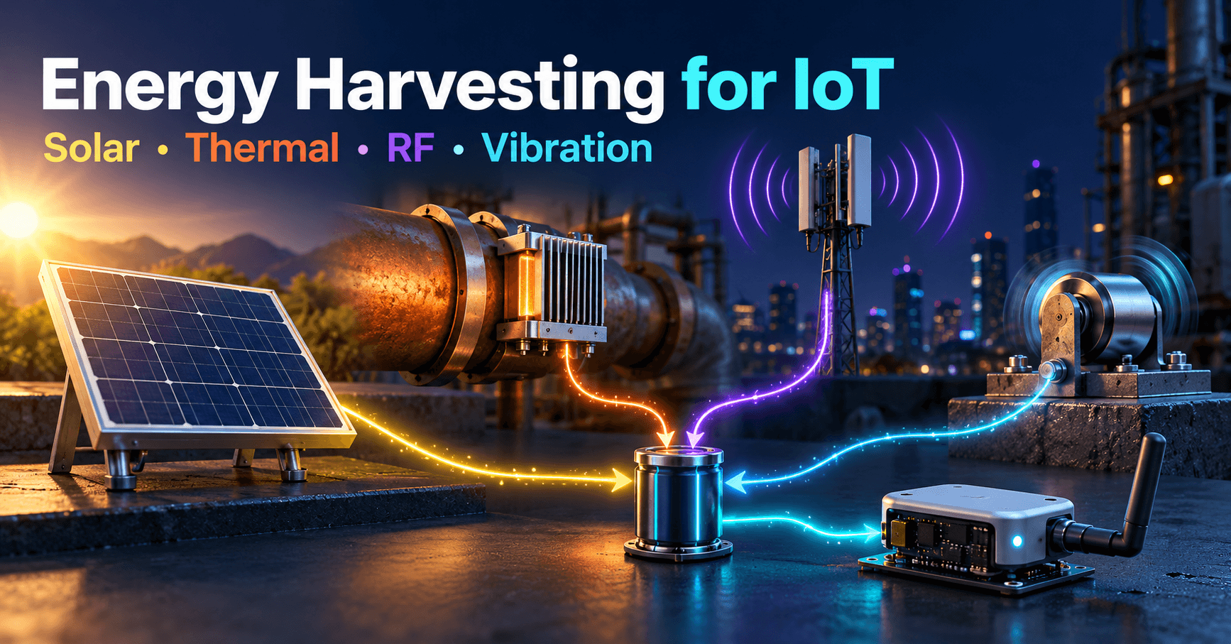
Contents & prerequisites
Why Energy Harvesting Matters for IoT
The battery replacement problem at scale
A single coin-cell-powered sensor that dies after two years is a minor annoyance. A fleet of 20,000 of them, scattered across a pipeline right-of-way or embedded in concrete, is an operational liability. Truck rolls to swap batteries cost far more than the hardware itself once you factor in labor, vehicle time, and access logistics (confined spaces, rooftop units, buried assets). For many deployments the battery is not a component — it's a recurring service contract you didn't price into the product. Energy harvesting exists to remove that line item entirely, or at minimum to stretch replacement intervals from years to "never, under warranty."
Energy harvesting vs. traditional power in constrained devices
Harvested power is a different animal from a regulated battery rail. It's intermittent, low-amplitude, and often arrives as a trickle of microwatts to milliwatts rather than the steady milliamps a battery can source on demand. This matters most for the constrained devices this field already has vocabulary for — the Constrained Devices: RFC 7228 Class 0, 1, 2 Definitions classification is a useful lens here, because a Class 1 node with tens of kilobytes of RAM and a duty-cycled radio is exactly the profile that can live on harvested energy, while a Class 2 device running continuous connectivity usually cannot without a much larger harvesting area or a hybrid source.
Lifetime and maintenance cost reduction
The pitch isn't "free energy" — it's deferred and reduced maintenance cost. A correctly engineered harvesting system shifts the economics from recurring OpEx (battery swaps) to one-time CapEx (harvester + storage element), with the storage element being the only part with a finite life, and even that can be a 10+ year supercapacitor or a slow-fade secondary cell rather than a primary battery that hits a cliff.
Solar Energy Harvesting
Photovoltaic cell fundamentals and efficiency ratings
A photovoltaic cell converts incident photons to current proportional to irradiance, with efficiency (the fraction of incident energy converted to electrical energy) typically in the 15–24% range for crystalline silicon and lower for thin-film and amorphous cells. Check the specific cell's datasheet for its efficiency and open-circuit voltage curve versus temperature — efficiency drops as cell temperature rises, which matters for outdoor enclosures that bake in direct sun.
Indoor vs. outdoor light conditions and output variability
This is where solar harvesting gets misunderstood. Outdoor full sun delivers on the order of 1000 W/m², but indoor office lighting delivers roughly three to four orders of magnitude less, and the cell's output doesn't scale linearly across that range because of diode characteristics near open-circuit voltage. A panel sized for a bright windowsill can produce next to nothing on a bookshelf. Always characterize the actual deployment light condition — ideally with a lux meter and the cell's own I-V curve at that irradiance — rather than extrapolating from the outdoor-rated figure on the datasheet.
Integration with power management and storage circuits
Solar harvesters need a charge path: a low-dropout or switching regulator sized for the panel's maximum power point, reverse-current protection so storage doesn't discharge into the panel at night, and overvoltage protection for open-circuit conditions. Most commercial energy-harvesting PMICs integrate these functions along with battery/supercap charge management — evaluate against your specific storage chemistry's charge profile in its datasheet.
Form factors: thin-film, rigid panel, and wearable solar
Rigid panels give the best efficiency-per-area and are the default for fixed outdoor installs. Thin-film and flexible panels sacrifice efficiency for conformability — useful on curved enclosures or wearables — and amorphous silicon variants tend to perform relatively better than crystalline under low, diffuse indoor light, which is worth testing for indoor asset trackers.
Thermoelectric Generators (TEG)
Seebeck effect and temperature delta requirements
A TEG generates voltage proportional to the temperature difference (ΔT) across its two faces via the Seebeck effect. Usable output generally requires a ΔT of at least several degrees Celsius sustained across the module — a TEG sitting in thermal equilibrium with its environment produces nothing, so the design problem is really a heat-flow problem: maintaining a cold side and hot side that don't equalize.
Real-world applications: industrial equipment, pipe monitoring
TEGs shine on industrial assets with a stable, persistent temperature gradient: steam pipes, motor housings, exhaust ducting, or refrigeration lines. Pipe monitoring is a common case — strap a TEG to a hot pipe with ambient air as the cold side, and you get a continuous few milliwatts without any moving parts, which suits condition-monitoring sensors reporting every few minutes.
Power output limitations and efficiency curves
TEG conversion efficiency is low, typically a few percent, and output scales roughly with ΔT squared divided by internal resistance in the module's operating region — consult the specific module's power-vs-ΔT curve in its datasheet rather than assuming linearity. Don't expect more than low milliwatts from small-form-factor TEGs at modest industrial ΔTs.
Thermal interface design and placement strategies
The TEG's output is only as good as its thermal contacts. Use thermal paste or pads rated for the operating temperature, maximize hot-side contact area, and add a heat sink with fins or airflow on the cold side to keep ΔT from collapsing as heat conducts through. A poorly mounted TEG with great thermal interface material on paper can underperform a mediocre TEG with a well-designed heat sink by a wide margin.
RF Energy Harvesting
Ambient RF scavenging from cellular and broadcast signals
Ambient RF harvesting captures energy from cellular base stations, broadcast TV/radio, or Wi-Fi. Realistic ambient power density is extremely low — microwatts per square centimeter at best, dropping fast with distance from the transmitter — so this method suits only ultra-low-duty-cycle sensing, not continuous operation.
Rectifier circuits and impedance matching
An RF harvester needs an antenna matched to the target band, a rectifier (typically a Schottky diode or charge-pump rectifier array) to convert AC to DC, and a matching network tuned for the expected source impedance and frequency. Mismatch losses at these power levels are proportionally brutal, so simulate or measure the matching network rather than assuming nominal 50 Ω behavior holds at microwatt signal levels.
Range limitations and practical power budgets
Dedicated RF transmitters (as opposed to ambient scavenging) can deliver more predictable power at short range — centimeters to a few meters — which is the basis of RFID and some proximity-powered sensors. Beyond a meter or two from a dedicated source, or relying purely on ambient signals, expect power budgets in the low microwatts, suitable only for intermittent wake-and-report cycles.
Co-design with ultra-low-power wireless protocols
RF harvesting only works if the radio protocol's duty cycle matches the harvested trickle. This is the same trade-off space covered in IoT Connectivity Trade-Offs: Range, Bandwidth, Power, Cost — a protocol with aggressive sleep states and short, infrequent transmissions is mandatory; anything resembling continuous connectivity will outpace RF-harvested supply.
Vibration Energy Harvesting
Piezoelectric and electromagnetic transducers
Piezoelectric transducers generate voltage from mechanical strain and suit higher-frequency, lower-amplitude vibration; electromagnetic transducers (a magnet moving through a coil) suit lower-frequency, higher-amplitude motion. Choice depends on the vibration spectrum of the host machinery, which should be measured, not assumed.
Frequency response and resonance tuning
Most vibration harvesters are resonant devices tuned to a narrow frequency band — output falls off sharply away from resonance. If the host equipment's vibration frequency drifts with load or wear, a fixed-resonance harvester can lose most of its output; some designs use tunable or wideband (nonlinear) mechanisms to tolerate this drift.
Applications in machinery, transportation, and structural monitoring
Rotating machinery (pumps, motors, compressors) and transportation assets (rail cars, truck trailers) provide strong, fairly consistent vibration sources. Structural monitoring on bridges or buildings deals with lower-amplitude, more sporadic excitation, which generally demands larger transducers or hybridization with another source.
Bandwidth requirements and energy storage
Vibration events are often bursty rather than continuous, so the harvested energy needs a buffer — a supercapacitor sized to absorb peak output and release it during the quieter intervals between a machine's duty cycles.
Hybrid Harvesting and Power Management
Multi-source architectures and switching strategies
Combining two or more sources (commonly solar plus TEG, or solar plus vibration) hedges against any single source going quiet — clouds roll in, machinery idles, RF conditions change. A hybrid PMIC with multiple input rails and priority or summing logic lets the system draw from whichever source is active without manual switching.
Energy buffering: supercapacitors vs. secondary batteries
Supercapacitors handle fast charge/discharge cycles well and tolerate tens of thousands of cycles, but they have lower energy density and higher self-discharge than secondary (rechargeable) batteries. Secondary batteries (thin-film lithium, LiFePO4) store more energy per volume for bridging longer gaps — a cloudy week, a shutdown machine — but degrade with cycle count and extreme temperature. Many hybrid designs use a small supercapacitor as the immediate buffer in front of a secondary battery as the long-term reservoir.
MPPT (Maximum Power Point Tracking) control
Solar and, to a lesser extent, TEG sources have a nonlinear I-V curve with a maximum power point that shifts with irradiance or ΔT. A simple linear regulator leaves power on the table; an MPPT-capable PMIC perturbs the operating point to track the maximum, which matters more as harvested power shrinks and every microwatt counts.
Supply-side power conditioning for intermittent sources
Downstream of the harvester and buffer, the MCU needs a supply that tolerates brownouts gracefully — a boost converter with undervoltage lockout and hysteresis prevents the system from browning out mid-transmission and corrupting state. This conditioning layer is as important to budget for as the harvester itself.
Selection Criteria and Trade-Offs
Environmental availability assessment
Before choosing a harvester, instrument the deployment site: measure actual lux levels, ΔT across candidate mounting surfaces, ambient RF power density, and vibration spectra with real sensors over a representative period — not assumptions from the asset's nominal specs.
Cost vs. power density vs. form factor
Solar generally offers the best cost-per-microwatt in bright environments; TEG and vibration harvesters cost more per unit of area but work where light is unavailable; RF harvesting is cheapest to add but offers the least power. Form factor constraints (a flat enclosure face for solar, a hot surface for TEG, a vibrating mount for piezo) often decide the question before cost does.
Application duty cycle alignment
Match the harvester's average power output to the sensor's average power draw, not its peak draw — a duty-cycled sensor that wakes for 50 ms every 10 minutes has a vastly lower average budget than its active-mode current suggests, which is often the deciding factor in whether harvesting alone suffices. This duty-cycle math is the same discipline used in broader Energy Management IoT: Sub-Metering, BEMS Integration deployments, where load profiling drives sizing decisions.
Integration complexity with MCU and RF modules
Factor in the engineering cost of the harvesting front end itself — custom matching networks for RF, thermal interface qualification for TEG, resonance tuning for vibration — against a simpler primary-battery design. For gateway-class devices with steady mains or PoE power, per the tiers in IoT Device Classification: Constrained, Gateway, Cloud, harvesting is rarely worth the complexity; it earns its keep specifically on constrained, battery-averse endpoints.
In nearly every realistic deployment, the answer to "can harvesting alone power the sensor" is no on its own — some buffer, whether a supercapacitor or secondary battery, is required to bridge the gap between an intermittent harvest and the device's actual duty cycle, and that buffer, not the harvester, is usually the component that ends up defining the product's real service life.
Learning
Sign in to track your progress.
Evidence
Public projects engineers linked to Energy Harvesting: Solar, TEG, RF, Vibration for IoT.
No engineer has linked a project to this topic yet. Built something that proves it? Add the project and tag it with iot-connectivity-energy-harvesting-solar-teg-rf-vibration-for-iot — it then shows here and on your public profile.