
Chromatograph and Analyzer System Interface
Learn how chromatograph and analyzer signals, wiring, and scaling integrate with PLC and DCS systems for reliable process measurement.
Contents & prerequisites
Overview of Chromatograph and Analyzer Systems
Purpose and industrial applications
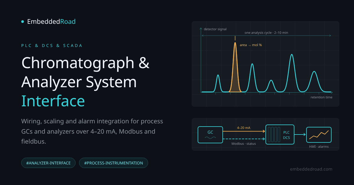
Process gas chromatographs (GCs), continuous emissions monitors (CEMs), pH/conductivity analyzers, and online spectrometers exist to answer one question a basic transmitter cannot: what is actually in the stream, not just how much of it is flowing. In refining, natural gas custody transfer, petrochemical production, and power plant emissions monitoring, these instruments determine product composition, BTU content, contaminant levels, or regulatory compliance values in near real time. Unlike a pressure or temperature transmitter that produces a continuous reading, a chromatograph performs a cyclic analysis — injecting a sample, separating components over a column, and reporting a composition vector once every 2 to 10 minutes depending on the application.
Role in process monitoring and quality control
The analyzer's output typically feeds two destinations: a local operator display for the lab or unit operator, and the control system, where the composition data drives feedback control (blending ratios, combustion trim, distillation cut points) or compliance logging. The control engineer's job is not chemistry — it's ensuring the data arrives in the DCS or PLC at the right scale, at the right time, with known data quality, and with every fault condition (stale data, calibration failure, out-of-range sample) visible as an alarm rather than silently accepted as a good reading.
Integration with control systems
Integration happens at three levels: the physical signal (analog, discrete, or serial), the logical representation of that signal as a tag with engineering units, and the supervisory logic that uses the tag for alarming, trending, and control. A mistake at any one level propagates upward — a wrong analog range in the I/O module produces a wrong tag value no matter how correct the downstream PLC logic is.
Signal Types and Output Protocols
Analog output signals (4–20 mA, 0–10 V)
Most analyzers still provide at least one 4–20 mA output per measured component or a composite "quality" signal, scaled over a configurable range (e.g., 0–100% methane, 0–5000 ppm H₂S). The 4 mA live zero lets the receiving system distinguish a true zero reading from a broken wire or powered-down transmitter — a dead loop reads 0 mA, not 4 mA. 0–10 V outputs are less common in hazardous areas because voltage signals are more susceptible to IR drop over long cable runs and don't offer the same built-in fault detection.
For every 4–20 mA loop, check the voltage budget with the same loop analysis used in basic circuit theory (see Kirchhoff's Voltage Law (KVL) and Mesh Analysis): at the highest current the loop must carry (20 mA, or 21–22 mA when the transmitter signals a fault), the supply voltage minus the drops across the wiring, any intrinsic-safety barrier, and the input module's sense resistor must still leave the transmitter at least its minimum operating voltage.
Digital and serial communications (Modbus, Foundation Fieldbus)
Modern GCs and analyzers expose Modbus RTU (RS-485) or Modbus TCP, and in some DCS-centric plants, Foundation Fieldbus H1, which carries not just the primary value but diagnostic status, multiple component concentrations, and configuration parameters over a single multidrop cable. This is the preferred method when more than two or three values need to come from one instrument — wiring sixteen separate 4–20 mA loops for a sixteen-component GC is impractical. The trade-off is added complexity: now the engineer must manage register maps, polling rates, and communication timeouts instead of simple current loops.
Pulse and frequency outputs
Some analyzers, particularly those with integrated flow correction or BTU calculation, provide pulse outputs representing energy or volume totals. These need a high-speed counter input card rather than a standard analog input, and the PLC program must account for pulse weight (units per pulse) and rollover behavior in the totalizer.
Status and alarm contact closures
Nearly every analyzer provides dry contact outputs for conditions like "analyzer fault," "calibration in progress," "sample out of range," or "maintenance mode." These are frequently wired to discrete inputs and are the single most under-utilized integration point — ignoring them means the control system treats a mid-calibration reading exactly like a valid process measurement.
Hardware Interface Architecture
Analog input module requirements and resolution
A 12-bit analog input card resolves a 4–20 mA signal into roughly 4096 counts, giving about 0.004 mA resolution — fine for most applications, but if the measured range is narrow (say 0–50 ppm over a 4–20 mA span), confirm the I/O module's actual effective resolution in its datasheet rather than assuming it matches the component's chemical precision. 16-bit cards are preferred for analyzer work because composition changes of interest are often a fraction of a percent.
Isolation and signal conditioning
Analyzers are frequently installed in classified (hazardous) areas and may be powered from a different ground reference than the control system cabinet. Isolated input modules or external isolators prevent ground loops, ground potential differences, and in the worst case, damage from a fault current finding an unintended path through the signal cable. For low-level or multi-terminal measurement circuits, treating the analyzer-to-barrier-to-I/O path as a two-port network — with defined input/output impedance relationships — helps when selecting isolation amplifiers or converters; the formal framework is covered in Two-Port Network Parameters: Z, Y, H, ABCD, which is useful when a vendor specifies an isolator only in terms of input/output impedance and you need to confirm loop compatibility.
Communication gateways and protocol converters
When the analyzer speaks Modbus RTU and the DCS backbone is Modbus TCP, Profibus, or a proprietary fieldbus, a protocol gateway is required. Budget for gateway-induced latency (often 100–500 ms per poll cycle, confirm in the gateway's datasheet) when the analyzer value feeds a fast control loop — it normally shouldn't, since analyzer cycle times are already in the minutes range, but verify this assumption explicitly rather than inheriting it.
Power supply and grounding considerations
Confirm whether the analyzer's 4–20 mA output is loop-powered (sourced by the receiving system) or self-powered (sourced by the analyzer, with the input module only sinking current). Mixing these up is a common commissioning error — wiring a self-powered (4-wire, active-output) analyzer to an input channel that also supplies loop power, or a passive 2-wire output to an input that doesn't, can produce a signal that reads full scale or zero regardless of actual process value.
Software Configuration in PLC/DCS
Tag definition and scaling of instrument outputs
Every analog point needs an explicit raw-to-engineering-unit scale matching the analyzer's configured output range exactly — not the instrument's physical measurement range, but what it was configured to transmit, which is documented in its configuration report, not its generic datasheet.
// Example scaling for a GC methane composition output
// Analyzer configured: 4 mA = 0% CH4, 20 mA = 100% CH4
// Raw input (12-bit, 4-20mA card): 819 = 4mA, 4095 = 20mA

RAW_SPAN   := 4095 - 819;      // = 3276
EU_SPAN    := 100.0 - 0.0;     // engineering units span
CH4_Pct    := ((Raw_Input - 819) * EU_SPAN / RAW_SPAN) + 0.0;

CH4_Fault := Raw_Input < 750;  // below live zero (~3.66 mA) -> wiring/loop fault
Alarm thresholds and setpoint logic
Separate process alarms (composition out of spec) from instrument alarms (analyzer fault, stale data, calibration in progress). Gate any control action that depends on analyzer output with a "data valid" bit driven by the status contact closures described earlier — a stale reading held at its last good value should never silently continue driving a control loop.
Data logging and trending
Log both the raw analyzer cycle data and the interpolated/held value the control system uses between cycles, since regulatory and process-troubleshooting reviews often need to distinguish an actual process excursion from an analyzer reporting delay.
Calibration verification and diagnostics
Most GCs run automatic calibration cycles against a certified reference gas on a schedule (daily to weekly). Bring the calibration result (deviation from expected reference value) into the DCS as a trended value, not just a pass/fail bit, so drift trends are visible before they trip a hard alarm.
Wiring and Installation Best Practices
Cable routing and shielding
Route analyzer signal cables in dedicated trays separate from VFD and power cabling; maintain at least the separation distance specified in your plant's electrical installation standard (commonly referenced from IEEE 518 practice, confirm against your site standard). Shield grounded at one end only, typically the control room end, to avoid ground loop currents flowing through the shield.
Terminal block organization
Group analog, discrete, and communication terminals by analyzer and by signal type, with clear, consistent labeling matching the loop drawing. Fused terminal blocks on each analog input simplify isolating a faulted channel without disturbing adjacent loops.
Surge protection and EMI filtering
Install surge suppression on any cable run exposed to outdoor routing or near high-energy switching equipment; analyzer electronics are often more sensitive to transients than standard 4–20 mA transmitters due to onboard microprocessors and detectors.
Instrument location and sampling line considerations
Sample transport time (dead time from tap point to analyzer) directly adds to the effective response time the control system sees. A 30-meter sample line at low flow can introduce minutes of lag — document this transport delay alongside the analyzer's internal cycle time when tuning any control loop that uses the reading.
Troubleshooting and Maintenance
Common communication and signal faults
For analog loops: check for readings pinned at or near 0 mA (open loop, power loss, or reversed polarity on a protected transmitter), readings stuck at full scale (shorted loop or wrong loop-power configuration), or noisy fluctuation (grounding or shield fault). For serial links: verify baud rate, parity, and node address match on both ends before suspecting the physical layer; a surprising fraction of "communication failures" are configuration mismatches rather than wiring faults.
Verification of calibration drift
Compare the analyzer's automatic calibration deviation trend against maintenance records; a steadily increasing deviation over weeks usually indicates column degradation or detector aging rather than a sudden fault, and should trigger scheduled maintenance before the deviation forces an unplanned shutdown.
Response testing and system validation
Periodically inject a known reference sample and confirm the full chain — analyzer, wiring, I/O module, scaling, and displayed value in the HMI — matches the expected result within documented tolerance. Testing only the analyzer's local display without confirming the DCS-side value misses scaling and communication errors entirely.
Documentation and change management
Any change to an analyzer's configured output range must be mirrored in the PLC/DCS scaling configuration and recorded in the loop's as-built documentation. An unmanaged mismatch between field configuration and control system scaling is one of the most persistent root causes of silent measurement errors in analyzer integration.
Learning
Sign in to track your progress.
Evidence
Public projects engineers linked to Chromatograph and Analyzer System Interface.
No engineer has linked a project to this topic yet. Built something that proves it? Add the project and tag it with plc-dcs-chromatograph-and-analyzer-system-interface — it then shows here and on your public profile.