
VNA Calibration: SOLT, TRL, SOLR, LRM Methods
Compare VNA calibration methods—SOLT, TRL, SOLR, and LRM—to choose the right one for coaxial, on-wafer, or non-50-ohm RF measurements.
Contents & prerequisites
Why VNA Calibration Matters
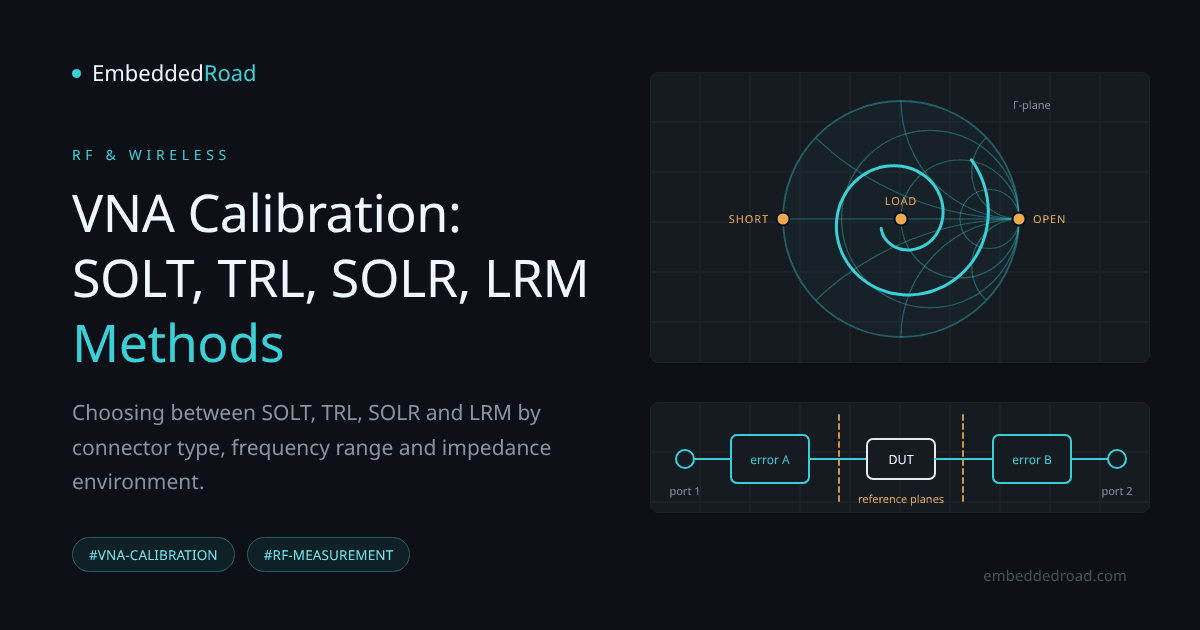
A vector network analyzer measures complex ratios of traveling waves at its test ports, but the raw numbers it reports include everything between the measurement reference plane inside the instrument and the device under test: cables, connectors, adapters, and the imperfect directivity of the internal couplers. Calibration is the process of characterizing that error network so it can be mathematically removed, leaving only the response of the DUT.
Error sources in VNA measurements
Three systematic error mechanisms dominate: directivity (leakage of the incident signal into the reflected-signal receiver), source/load mismatch (reflections at the port that re-reflect off the DUT), and frequency-tracking errors (gain and phase differences between the reference and test receivers). These are systematic — repeatable and correctable — as opposed to random errors like noise or drift, which calibration cannot fix. A raw S11 measurement of a well-matched DUT might show -25 dB instead of the true -40 dB purely because of residual directivity in the coupler; see the Decibel (dB): Voltage, Current, and Power Ratios article if you need a refresher on why that 15 dB gap matters in linear terms (it's roughly a 5x error in reflected voltage).
Impact of connector and transmission-line effects
Every adapter, connector interface, and length of cable between the VNA port and the DUT adds loss and phase delay that corrupts both magnitude and phase of S-parameters. A 2.92 mm-to-SMA adapter with 0.2 dB of loss doesn't just attenuate the signal — it also shifts the apparent impedance of everything beyond it. Connector repeatability (the variation from repeated mate/unmate cycles) sets a hard floor on achievable accuracy regardless of how good your cal standards are; a worn or gauge-out-of-spec connector can dominate the error budget above a few GHz.
Calibration plane definition and reference impedance
Calibration defines two things simultaneously: the reference plane (the exact physical point where "DUT" begins) and the reference impedance (almost always 50 Ω, though TRL calibrations are an exception discussed below). Everything measured is relative to that plane and that impedance. If your calibration standards are defined at the end of your cables, your reference plane is there — not at the DUT's pins — and you'll need a separate deembedding step to move it further.
SOLT Calibration: The Industry Standard
Short, Open, Load, Thru kit composition
SOLT uses four known standards per port pair: a Short (ideally Γ = -1), an Open (ideally Γ = +1, with a frequency-dependent fringing-capacitance model in practice), a Load (ideally Γ = 0, a precision 50 Ω termination), and a Thru connecting the two ports directly. Commercial cal kits ship with characterization files (polynomial coefficients for open fringing capacitance, short inductance, etc.) that the VNA uses instead of assuming ideal behavior — always load the correct kit file for your specific connector family and kit serial number, as generic models introduce errors that grow with frequency.
12-error-term model and two-port error correction
A full two-port SOLT calibration solves for twelve error terms — six per direction (forward and reverse), covering directivity, source match, load match, reflection tracking, transmission tracking, and isolation. This is the classic two-port error model you'll find in any VNA application note; conceptually it's equivalent to characterizing an unknown error two-port network in cascade with the DUT, which is why familiarity with Two-Port Network Parameters: Z, Y, H, ABCD representations helps when you need to understand how calibration math de-embeds the DUT from the surrounding error boxes.
When SOLT works best and its limitations
SOLT is the default choice for connectorized measurements with standard coaxial connectors (2.4 mm, 3.5 mm, N-type, SMA) up to tens of GHz, because cal kits are commercially available, well-characterized, and the procedure is fast. Its weakness is that it depends entirely on the accuracy of the standards' models — if the Open's fringing capacitance model is wrong, or the Load isn't truly 50 Ω at high frequency, the calibration inherits that error silently. SOLT also requires a physical Thru connection between ports, which isn't always possible.
Repeatability and connector assumptions
SOLT assumes your standards and your DUT use identical, mechanically repeatable connectors. Mixed connector types (e.g., calibrating in 3.5 mm but measuring a DUT in SMA) introduce an impedance discontinuity that no calibration can remove unless you insert a characterized adapter and deembed it separately.
TRL Calibration: Transmission Line Method
Thru, Reflect, Line architecture
TRL replaces the Load standard with a second transmission line of different length. It uses a Thru (zero-length or known-length line), a Reflect (any high-reflection standard — short or open — whose exact value doesn't need to be known precisely, only that it's the same at both ports), and a Line (a transmission line of different length than the Thru, ideally giving 20°-160° of phase difference at the calibration frequency).
Cascaded-line phase-length extraction
Because TRL never requires a precisely-known Load, it sidesteps the biggest source of SOLT error. Instead, it extracts the propagation constant directly from the measured phase difference between the Thru and Line standards. The mathematics treats the Thru-Line pair as cascaded unknown networks and solves for the error boxes algebraically, which is why TRL is often described as "self-calibrating" with respect to the line standard's characteristic impedance.
Characteristic impedance and phase velocity measurement
The reference impedance after TRL calibration is whatever characteristic impedance the Line standard has — not necessarily 50 Ω. This is a feature, not a bug: for on-wafer or fixtured measurements in media where a true 50 Ω load standard is hard to realize (microstrip on an unfamiliar substrate, for example), TRL lets the line itself define the impedance reference, and that impedance can be measured or computed from the line's geometry and the substrate's dielectric properties afterward.
Advantage in non-50Ω systems and high frequencies
TRL shines above roughly 20-30 GHz and in non-coaxial environments (waveguide, microstrip, coplanar waveguide) where a wideband, accurate Load is difficult to manufacture but a low-loss transmission line is easy to fabricate in the same medium as the DUT. The trade-off is that a single Line standard only covers about an 8:1 frequency span (the 20°-160° phase window); broadband TRL calibration requires multiple Line standards of different lengths, stitched together.
SOLR and LRM: Practical Variants
SOLR (SOLT + Reciprocal): eliminating Thru kit
SOLR keeps the Short, Open, and Load standards but replaces the precisely-known Thru with any reciprocal two-port network (S21 = S12, magnitude and phase need not be known). This matters when a true zero-length or defined Thru is physically impossible — for example, a non-insertable DUT whose ports share the same connector gender, or an in-fixture or on-wafer setup where the ports face awkward directions. The trade-off is a slightly more complex error-term solution, a requirement that the "unknown thru" truly be reciprocal (S21 = S12), and the need to know its approximate electrical length so the algorithm picks the correct root; a very lossy unknown thru increases uncertainty.
LRM (Line-Reflect-Match): coplanar and stripline environments
LRM uses a Line, a Reflect, and a Match (a resistive load, similar in spirit to SOLT's Load but only needed at one length/position rather than needing multiple line lengths like TRL). It's the standard choice for on-wafer probing with coplanar ground-signal-ground probes, where fabricating multiple long transmission lines on a wafer wastes die area and a broadband match standard can be realized as a thin-film resistor calibrated against DC and low-frequency measurements.
When to use each method
Choose SOLR when you need SOLT's familiar Short/Open/Load but can't realize a defined Thru. Choose LRM when you're on-wafer or in a tightly-constrained fixture where TRL's multiple line lengths won't fit, and a resistive match standard is easier to fabricate than a second line.
Trade-offs between hardware and software correction
SOLT leans hardest on precisely modeled hardware standards; SOLR relaxes only the Thru, LRM needs just one accurately known Match, and TRL relies least on standard definitions, deriving its reference from the line itself. The practical trade-off is procurement and calibration-kit cost versus measurement setup flexibility.
Comparing Calibration Methods
Accuracy versus frequency range
SOLT is excellent from DC/low MHz up to the point where Open/Short models become unreliable (often tens of GHz, check your kit's datasheet for the validated range). TRL achieves the best accuracy at millimeter-wave frequencies because it depends on geometry, not lumped-element models. LRM sits between the two, trading TRL's self-calibrating impedance reference for a smaller physical footprint.
Kit cost and measurement complexity
SOLT kits are the most commercially available and cheapest for standard coaxial connectors. TRL and LRM standards are frequently custom-fabricated (especially for on-wafer or waveguide work), raising upfront cost but often paying off in accuracy for a specific fixture or wafer process.
Fixture deembedding and reference planes
All four methods define a reference plane at the calibration standards. If your DUT sits behind a test fixture (PCB launch, probe-to-pad transition), you'll typically need an additional deembedding step — either by including fixture-equivalent standards in the cal kit or by post-processing with measured or simulated fixture S-parameters — regardless of which calibration method you used.
Connector type constraints
SOLT and SOLR are most at home with connectorized, mate/unmate-capable interfaces, though both also run on-wafer against impedance-standard substrates (SOLR is popular there precisely because its thru can be any reciprocal path between the probes). TRL and LRM are agnostic to connector type and are routinely used with microstrip test fixtures, coplanar probes, and waveguide flanges where there's no "connector" in the coaxial sense at all.
Practical Calibration Workflow
Setup checklist: connector cleanliness and adapter loss
Inspect connectors under magnification for bent pins or worn plating before every calibration session. Use a torque wrench rated for your connector type — overtightening is as damaging as undertightening. Characterize or at minimum document the loss of any adapters used between the VNA port and the calibration plane; if the adapter isn't part of the cal kit's characterized standards, it introduces unremoved error.
Choosing the right method for your application
Start with SOLT if you're doing connectorized coaxial measurements with a standard kit and a reachable Thru. Move to SOLR if the Thru is impossible but Short/Open/Load are available. Use TRL if you're above ~20 GHz, working in waveguide or an unconventional transmission medium, or need the most accurate impedance reference possible. Use LRM for on-wafer and space-constrained fixture work.
Validation and residual-error assessment
After calibrating, always measure a known verification standard that was not part of the cal kit — an airline, a precision attenuator, or a second Short/Open/Load set with independently traceable characterization. Check that a matched termination reads an S11 below about -35 to -40 dB, i.e. return loss better than 35 to 40 dB (or whatever your calibration's expected residual directivity predicts), and that a verified attenuator's insertion loss matches its specified value within the VNA's rated uncertainty.
Common pitfalls and troubleshooting
The most common failure is using the wrong cal-kit definition file (wrong connector gender, wrong kit serial number) — this produces a calibration that looks clean on the standards themselves but gives wrong DUT data. Another is calibrating at one power level or IF bandwidth and measuring at another, which can reveal nonlinearity or noise-floor issues masked during cal. Finally, watch for calibration drift from temperature changes in long measurement sessions — recalibrate if ambient temperature drifts more than about 1 °C from the calibration temperature (the window most VNA uncertainty specifications assume), especially above 20 GHz where phase sensitivity to cable flexure and thermal expansion becomes significant.
Learning
Sign in to track your progress.
Evidence
Public projects engineers linked to VNA Calibration: SOLT, TRL, SOLR, LRM Methods.
No engineer has linked a project to this topic yet. Built something that proves it? Add the project and tag it with rf-and-vna-calibration-solt-trl-solr-lrm-methods — it then shows here and on your public profile.