
ESD Immunity: IEC 60601-1-2 Basic/Enhanced Performance
Learn IEC 60601-1-2 ESD immunity voltage levels, Basic vs Enhanced Performance criteria, and circuit design methods for medical devices.
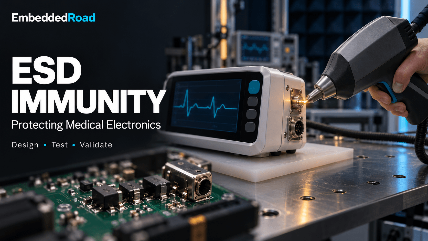
Contents & prerequisites
Why ESD immunity matters in medical device safety
Electrostatic discharge (ESD) immunity determines whether a medical device keeps working — or fails safely — when a charged operator, patient, or object dumps several kilovolts into it in a fraction of a microsecond. A single discharge event lasts under 100 ns but can inject peak currents above 30 A into a connector shell, and the resulting electromagnetic transient couples into signal traces, resets microcontrollers, and corrupts data long before any visible damage occurs.
Static discharge as a failure mechanism in patient care environments
Hospitals and home-care settings generate static charge routinely: wheeled equipment crossing vinyl flooring, synthetic bedding, low-humidity HVAC systems, and gloved hands all build triboelectric charge that discharges the moment someone touches a metal connector or button. For a device monitoring a sedated or anesthetized patient, a brief processor reset is not a cosmetic glitch — it is a gap in surveillance. A pulse oximeter or capnograph that reboots silently after an ESD event can display a frozen last-known value while the patient's condition changes, which is why neonatal monitoring parameters such as SpO2 and respiration rate carry explicit continuity expectations in their risk files, not just accuracy specs.
Regulatory classification: Basic Performance vs Enhanced Performance
IEC 60601-1-2 does not set one ESD level for every device; it requires the manufacturer to declare whether ESD immunity testing demonstrates Basic Performance or Enhanced Performance, and that declaration cascades into the required test voltage, the acceptable pass criteria, and the depth of the risk justification a notified body will expect. Basic Performance means the device may show a degraded or stopped function during the discharge provided it recovers without operator intervention and without creating a hazard. Enhanced Performance — a term borrowed from the essential-performance concept in IEC 60601-1 — means the specific function tied to patient safety must not be interrupted at all during the test.
Risk management integration with EMC immunity requirements
The performance level is not an engineering preference; it is an output of the risk management file required by ISO 14971. Electromagnetic compatibility (EMC) immunity requirements, including ESD, feed into the same hazard analysis that covers mechanical, electrical, and biological risks, and the ESD test plan should trace back to specific hazardous situations — not just a generic "device shall withstand ESD" statement.
How IEC 60601-1-2 defines ESD test levels and performance criteria
IEC 60601-1-2 adopts the test method of IEC 61000-4-2 and layers medical-specific performance criteria on top of it. The standard specifies the discharge voltages; the manufacturer's risk assessment specifies what counts as acceptable device behavior during and after each discharge.
Basic Performance: ±2 kV contact, ±2 kV air discharge requirements
The minimum immunity test level under IEC 60601-1-2 for most enclosure points is ±2 kV contact discharge and ±2 kV air discharge, with some editions and specific point classes requiring higher air-discharge levels depending on the applicable edition's test matrix. At this level, the device must not produce a hazardous output, but temporary loss of function — a display blank, an alarm mute, a reboot — can be acceptable if risk analysis shows no patient harm results and the device recovers to normal operation without manual intervention beyond power cycling, where permitted.
Enhanced Performance: ±4 kV contact, ±8 kV air discharge requirements
Enhanced Performance testing steps up to ±4 kV contact discharge and ±8 kV air discharge. This level is reserved for functions the risk file identifies as essential performance — functions whose loss or degradation could directly lead to unacceptable risk. A continuous ICP (intracranial pressure) waveform display used for real-time neurosurgical decision-making is a plausible candidate for Enhanced Performance treatment, since a dropout during active monitoring could mask a pressure spike; see how ICP monitoring literature frames continuous-trend requirements for the clinical rationale behind that kind of uptime demand.
Contact vs air discharge: which parts of the device must withstand each
Contact discharge is applied to conductive surfaces the operator can touch directly — metal housings, connector shells, exposed screws — and is the preferred, more repeatable method. Air discharge is reserved for surfaces that are not conductive or not directly accessible with the contact-discharge electrode, such as plastic enclosures, membrane keypads, and display bezels, where the electrode is brought close until a spark jumps the gap. Both methods must be applied to every point and surface normally accessible during use, including points accessible only after removing a user-replaceable part like a battery door.
Performance criteria: functional interruption vs permanent damage
A pass requires the device to either continue operating within specification throughout the discharge (Criterion A) or to experience a self-recovering degradation with no loss of essential function (Criterion B); permanent component damage, latch-up, or a need for operator reset to restore safe function is a fail regardless of which performance level applies.
When to apply Basic vs Enhanced ESD immunity requirements
The choice between Basic and Enhanced Performance is made during risk analysis, before a single test is run, and it should be defensible on paper independent of whatever the bench results turn out to be.
Clinical risk assessment driving performance level selection
Enhanced Performance is justified when an ESD-induced interruption of a specific function would plausibly lead to serious injury or death before a clinician could intervene. A continuous cardiac arrhythmia detector, a ventilator's breath-delivery control loop, or an infusion pump's flow-rate regulation are typical Enhanced-Performance candidates because their failure modes are fast and the compensating human response time is short. A device that only logs trend data for later clinician review, by contrast, can often justify Basic Performance because a momentary gap is recoverable from context.
Patient proximity and operator contact frequency classification
Devices with frequent direct patient or operator contact, or those used in high-static environments such as operating rooms and NICUs, warrant closer scrutiny even at Basic Performance levels, because real-world discharge events occur more often than the standard's test repetition count might suggest. A temperature sensor probe handled between patients, for instance, sees more discharge events per shift than a fixed bedside console, which argues for margin above the minimum test voltage even when Basic Performance is the declared level.
Device intended use environment: non-clinical vs clinical settings
IEC 60601-1-2 separates test requirements by environment — professional healthcare facility, home healthcare environment, and special environment — and the home environment carries its own immunity expectations reflecting less-controlled humidity and flooring than a hospital. A device intended for home use should not assume hospital-grade static control measures are present.
Documentation requirements for performance level justification
Notified bodies expect a written rationale, not a checkbox, linking each tested function to its performance-level classification, the specific hazard it mitigates, and the residual risk analysis after the declared performance criterion is met. This rationale typically lives in the risk management file and is cross-referenced in the EMC test report's device-under-test configuration section.
How to design circuits and layout to pass ESD immunity testing
Passing ESD testing is a layout and component-selection problem first, and a software-recovery problem second.
ESD protection device selection: diode arrays, TVS, suppressor specs
Transient voltage suppressor (TVS) diodes and diode arrays clamp transient voltage at I/O and connector interfaces before it reaches sensitive silicon. Key datasheet parameters to compare, not guess at, are listed below — consult the specific part's datasheet for clamping voltage and capacitance, since these vary by package and junction design.
| Parameter | Why it matters |
|---|---|
| Breakdown voltage | Must sit above the signal's normal operating range with margin |
| Clamping voltage at rated surge | Must stay below the downstream IC's absolute maximum rating |
| Junction capacitance | High-speed lines (USB, Ethernet) need low-capacitance arrays |
| Peak pulse current (8/20 µs) | Should exceed the expected discharge current for the declared test level |
PCB layout strategies: shielding, ground planes, guard traces
A continuous ground plane beneath connector regions gives discharge current a low-impedance return path away from signal layers, and guard traces tied to chassis ground around connector apertures intercept stray coupling before it reaches internal buses. Keep high-speed and analog sense lines away from board edges and connector shells, since these are the most probable discharge entry points.
Cable shielding and bonding for external connectors
External cable shields should bond to chassis ground at the point of entry, not at the internal PCB ground, so discharge current is diverted before it travels further into the circuit. An unterminated or floating shield is a common root cause of ESD test failures that otherwise pass on a bare board.
Component placement relative to high-voltage discharge points
Keep crystal oscillators, reset lines, and low-voltage logic physically distant from connector shells and screw bosses that are direct-contact discharge targets; a few millimeters of extra trace length combined with a local TVS diode often converts an intermittent reset into a clean pass.
What test setup and procedures require in your validation plan
Test equipment calibration and traceability requirements
The ESD simulator (the "ESD gun") must have current-waveform calibration traceable to a recognized standard, performed at intervals defined by the test lab's quality system, and the calibration certificate should be referenced in the test report alongside the discharge network's specified rise time and discharge resistance per IEC 61000-4-2.
Pre-test device conditioning and environmental controls
Testing is performed at controlled relative humidity, typically in the 30%–60% range specified by IEC 61000-4-2, because lower humidity increases charge accumulation and higher humidity suppresses it; the test report must record ambient temperature and humidity at the time of test.
Contact discharge vs air discharge apparatus configuration
Contact discharge uses a pointed electrode held against the surface with the discharge triggered electronically, giving repeatable results; air discharge uses a rounded electrode brought toward the surface at a controlled approach speed until breakdown occurs, which introduces more variability and is why air-discharge results are usually reported as the highest level passed rather than a single pass/fail at one voltage.
Multiple discharge points and repetition count per IEC 61000-4-2
IEC 61000-4-2 calls for a minimum of 10 discharges at each polarity and each test point for contact discharge, with similar repetition for air discharge, and the test plan must enumerate every accessible point and coupling plane configuration (horizontal and vertical coupling planes) rather than sampling a handful of convenient locations.
How to interpret test failures and define acceptable pass criteria
Transient measurement windows and settling time definitions
The pass/fail observation window extends from the moment of discharge through a defined recovery period — commonly tens of seconds for a microcontroller reboot cycle — and the risk file should state the maximum acceptable recovery time for each monitored function, not leave it to the test engineer's judgment on the day.
Distinguishing momentary malfunction from permanent degradation
A momentary malfunction that self-clears without data loss or hazardous output is typically acceptable at Basic Performance; a malfunction that requires power cycling, loses calibration data, or produces an erroneous reading after recovery is a fail at any performance level, because it introduces latent risk beyond the discharge event itself.
Post-test verification procedures and recovery documentation
After each discharge series, the device should be run through its full functional self-test, with particular attention to any safety-critical output that could silently drift out of calibration — an ESD event that shifts an analog front-end's offset without triggering an alarm is a worse outcome than an obvious crash.
Failure mode analysis linking ESD events to clinical risk
Every observed anomaly during testing should be traced to a specific clinical consequence in the risk file: does a 3-second display blank on a vital-signs monitor correspond to a documented acceptable risk, or does it violate the continuity assumption built into the alarm algorithm? Failure mode analysis that stops at "device rebooted, then recovered" without this linkage will not satisfy a technical file reviewer.
How ESD immunity integrates with broader EMC compliance strategy
Relationship to RF immunity, surge, and conducted immunity testing
ESD shares protection hardware and layout strategy with radiated RF immunity (IEC 61000-4-3), electrical fast transient immunity (IEC 61000-4-4), and surge immunity (IEC 61000-4-5) testing, since all four stress the same connector interfaces and grounding architecture; a TVS network sized for ESD clamping voltage often needs re-evaluation for surge energy handling, which is a different failure mode entirely.
Combined stress scenarios and worst-case interaction effects
Real clinical environments rarely deliver a single isolated stressor — an ESD event during active RF interference from a nearby electrosurgical unit is plausible — and while IEC 60601-1-2 tests each phenomenon separately, the risk file should consider whether marginal immunity margins on two tests independently could compound in the field.
Post-test aging assessment: whether ESD damage affects long-term safety
A device that passes functionally immediately after an ESD series can still have sustained latent damage to a TVS diode or input stage that shifts leakage current over months of field use; where repeated discharge exposure is expected (high-touch connectors, battery contacts), consider a post-test leakage and drift check beyond the immediate pass/fail observation.
Risk control verification documentation for notified body review
The technical file should present ESD immunity as one verified risk control among several, with a traceability matrix linking each hazard, the chosen performance level, the test evidence, and the design mitigation — layout, TVS selection, firmware recovery behavior — so a reviewer can follow the argument from hazard to verification without reconstructing it from raw test data.
Learning
Sign in to track your progress.
Evidence
Public projects engineers linked to ESD Immunity: IEC 60601-1-2 Basic/Enhanced Performance.
No engineer has linked a project to this topic yet. Built something that proves it? Add the project and tag it with medical-devices-esd-immunity-iec-60601-1-2-basicenhanced-performan — it then shows here and on your public profile.