
Protective Earth (PE): Green/Yellow Wire, Continuity < 0.1 Ω
How PE continuity testing with a <0.1 Ω threshold protects patients from shock, with four-wire measurement technique and risk-management integration.
Contents & prerequisites
Why PE Continuity Matters in Medical Device Safety
Role of PE in fault current diversion
The protective earth (PE) conductor — identified by its green/yellow insulation in nearly every national wiring code — exists to provide a deliberately low-impedance path from any accessible conductive part of a device back to the building's earth reference. If insulation fails anywhere in the device and line voltage finds its way onto the chassis, the PE conductor is what carries that fault current away from the enclosure and back toward the source, rather than through whatever (or whoever) happens to be touching the case. The protective mechanism depends entirely on the fault current being large enough, and the path being low-impedance enough, to trip an upstream overcurrent device — a circuit breaker or fuse — within milliseconds. A PE path with elevated resistance doesn't just weaken this protection; it can defeat it outright, because the fault current required to trip a breaker (often 10-20 A for a 15-20 A branch circuit) may never materialize if the earth path resistance is high enough to limit current below the breaker's threshold while still leaving a lethal touch voltage on the chassis.
Patient safety risk from high-impedance earth paths
Consider a chassis fault where line voltage (120 V or 230 V RMS) contacts an exposed metal part through a resistance of, say, 2 Ω in the fault itself. With an ideal PE path (near 0 Ω), the fault current is limited mainly by the fault resistance and source impedance, producing a large current that trips the breaker quickly. But if the PE conductor itself has degraded to several ohms — from corrosion, a loose crimp, or a cracked solder joint — the touch voltage appearing on the chassis under fault conditions can remain well above the 25 V AC / 60 V DC limits generally treated as safe for intact skin, and far above the microampere-level leakage currents considered safe for cardiac-connected patients. In a medical context this is not an abstract shock hazard: a patient connected via an ECG lead, a catheter, or any conductive accessory can become part of the current path, and currents on the order of 10 µA to 100 µA delivered directly to cardiac tissue (micro-shock) can induce fibrillation — orders of magnitude below what a healthy person would even perceive on intact skin.
Regulatory requirements (IEC 60601-1, IEC 61010-1)
IEC 60601-1, the base safety standard for medical electrical equipment, specifies PE continuity as part of its protective earthing requirements for Class I equipment, with the resistance limit and test current defined in the standard's clause on protective earth resistance (consult the current edition for the exact clause number and limit value applicable to your product category, since requirements differ slightly between general-purpose and particular standards in the 60601 series). IEC 61010-1, which governs laboratory and measurement equipment rather than direct-patient-contact devices, contains an analogous but not identical requirement. Engineers working on combination products — a point-of-care analyzer that is also a measurement instrument, for example — need to check which standard (or both) applies to a given accessible part, because the permissible resistance and test current can differ.
PE as a risk control measure in device design
Within a device's risk management file, PE integrity is rarely treated as a standalone feature. It is a risk control measure mapped directly against one or more identified hazards (electric shock, micro-shock to cardiac-connected patients) in the risk analysis required by ISO 14971. That mapping matters later: it means PE continuity testing isn't just a line item on a production test sheet, it's evidence that a specific risk control is functioning, and its failure rate and failure modes need to feed back into the risk file.
PE Continuity Testing Standards & Thresholds
Why < 0.1 Ω is the critical limit
The commonly cited 0.1 Ω limit (sometimes stated as 0.2 Ω or 0.3 Ω depending on mains cord length and the specific standard/edition) is not an arbitrary round number — it's derived from keeping the voltage drop across the PE conductor low enough, at expected fault currents, that touch voltage on the enclosure stays within safe limits, while also accounting for the resistance a well-made copper conductor of the specified gauge and length should exhibit. A typical 1.5-2.5 mm² PE conductor of 1-3 m length has an intrinsic resistance in the tens of milliohms; a measured value approaching or exceeding 0.1 Ω is a strong indicator of a bad connection — a corroded lug, a cold solder joint, a loose screw terminal — rather than normal conductor resistance. Exceeding the limit doesn't necessarily mean the device will shock someone tomorrow; it means the protective margin designed into the earthing system has been eroded, and the device fails the objective evidence requirement for the risk control to be considered effective.
Test voltage and measurement methodology
The standard approach injects a test current — typically specified as high enough to be representative of fault conditions but low enough to avoid damaging the conductor under test — at a low DC voltage, often cited around 1.5 V to 6 V DC range in various standards, with current held under 100 mA to 25 A depending on which standard and test class applies (IEC 60601-1's protective earth resistance test uses higher currents than a simple continuity check — verify the exact current and duration in the applicable clause before writing a test procedure). The key engineering point is that this is a four-terminal, low-voltage, moderate-current resistance measurement, not a high-voltage dielectric test — conflating the two is a common error for engineers new to electrical safety testing.
Differences between initial, post-sterilization, and retest requirements
A device validated for PE continuity at first article may degrade after repeated sterilization cycles (autoclave, EtO, or chemical disinfection), thermal cycling, or shipping vibration. Design verification should include PE continuity measured before and after the full specified sterilization/reuse cycle count, not just once off the bench. Production testing (100% or sampled, per your test plan) checks the as-built condition; periodic retest — whether in incoming inspection, preventive maintenance, or post-repair — needs its own defined interval and threshold, which should be documented in the device's service/maintenance manual.
Pass/fail criteria in IEC 60950-1 and medical-specific standards
IEC 60950-1 (legacy IT equipment safety standard, now largely superseded by IEC 62368-1) used a similar philosophy but different numeric limits and test currents than IEC 60601-1. Engineers porting designs or subassemblies between consumer/IT and medical product lines should not assume a PE test procedure validated under one standard automatically satisfies the other — the acceptance criteria, applied current, and measurement duration can all differ.
Testing Equipment & Procedure
Continuity testers: resolution, calibration, and traceability
A milliohm-resolution continuity tester (often built into a combined electrical safety analyzer alongside leakage current and dielectric withstand tests) needs calibration traceable to a national metrology institute, with calibration intervals and acceptance tolerances documented in your quality system. A tester with 10 mΩ resolution sounds adequate against a 100 mΩ limit, but accuracy specifications (not just resolution) at the low end of the range should be checked against the datasheet — a tester with ±5% accuracy at this range introduces real uncertainty into a pass/fail decision near the limit.
Four-wire measurement techniques to eliminate lead resistance
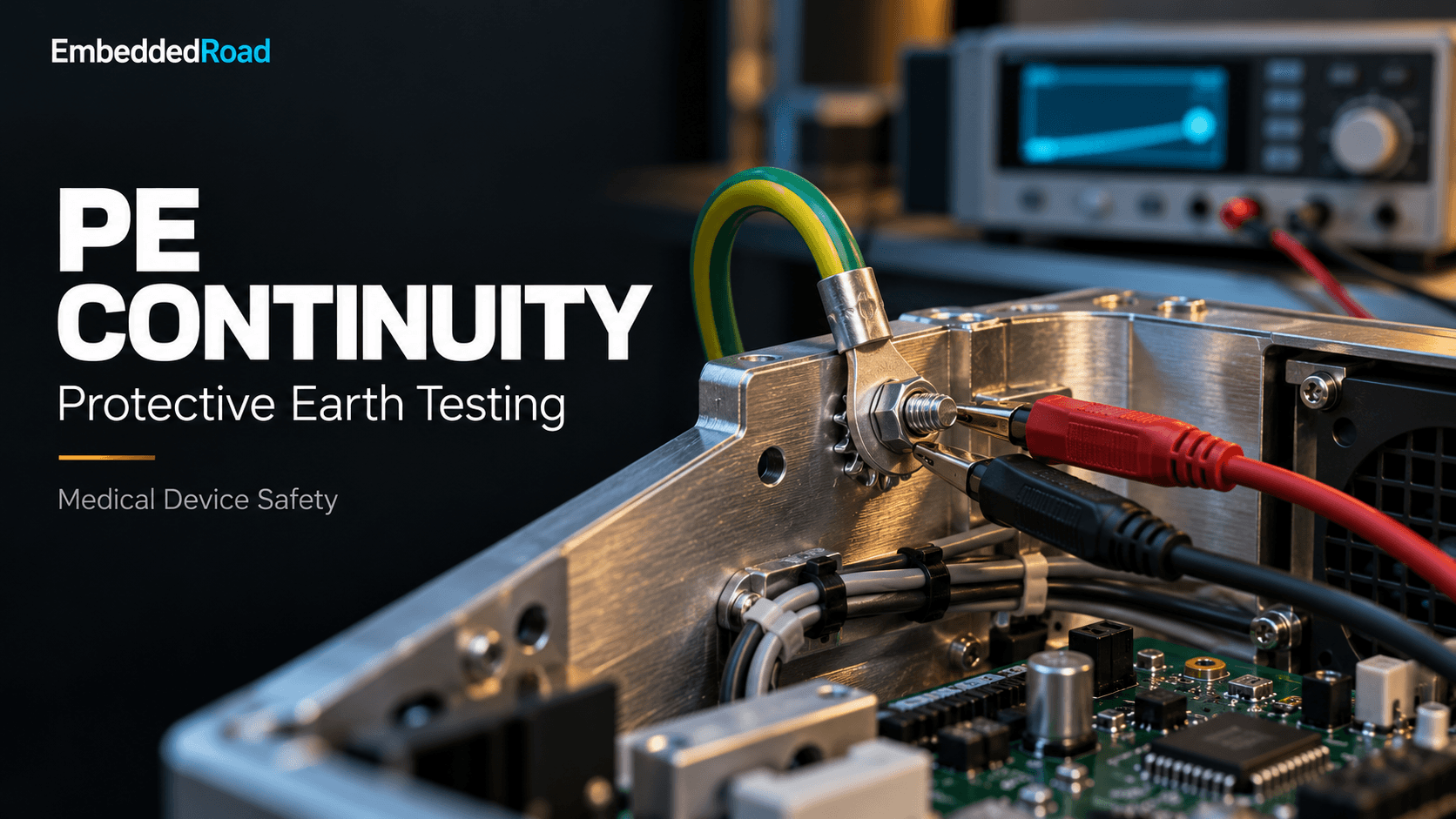
This is the single most common source of false passes and false fails in PE testing. A simple two-wire ohmmeter measurement includes the resistance of both test leads and their contact resistance at the probe tip — often tens to hundreds of milliohms, comparable to or larger than the 0.1 Ω limit itself. The fix is a Kelvin (four-wire) connection: separate current-carrying and voltage-sensing lead pairs, with the voltage sense points placed as close as possible to the actual test points on the device, so that lead and contact resistance drop out of the measurement. Example of why this matters:
Two-wire measurement:
  R_measured = R_PE_path + R_lead1 + R_lead2 + R_contact
  e.g. 0.05 Ω (true PE) + 0.08 Ω (leads/contacts) = 0.13 Ω -> FALSE FAIL

Four-wire (Kelvin) measurement:
  R_measured ≈ R_PE_path only
  e.g. 0.05 Ω -> correctly PASSES against 0.1 Ω limit
Any production fixture or handheld safety analyzer used for PE testing should be verified as a true four-wire instrument, with the sense leads clipped at the actual chassis/connector test point, not at the tester's output jacks.
Connection points: where to measure
Testing should proceed from the mains inlet PE pin outward to every accessible conductive part: main chassis/enclosure ground stud, metal connector shells (USB, serial, network), mounting hardware if conductive and user-accessible, and any metal part reachable without a tool per the applicable standard's definition of "accessible part." The typical order is inlet-to-chassis first (the primary path), then chassis-to-each-peripheral-connector-shell, since a failure at the chassis stage makes downstream measurements moot and should halt the test sequence rather than continuing to log failures against an already-failed primary path.
Documentation and acceptance limits for production testing
Each measured point needs its own recorded value against its own limit — not just an aggregate pass/fail — because trending an individual connector's resistance over a production run is how slow degradation (a crimping tool going out of calibration, a plating supplier change) gets caught before it becomes a field failure.
Integration into Risk Management Strategy
PE continuity as FMEA control point
In a device FMEA, "PE conductor open or high-resistance" is a failure mode with a specific effect (loss of fault current diversion, chassis becomes live under single-fault condition) and should be tied to a detection control — 100% production PE continuity test — with an associated detection ranking. If PE testing is only sampled rather than 100%, that choice needs explicit risk justification, because an undetected single bad unit in an untested sample is a direct path to the hazard the control was meant to prevent.
Defining risk acceptance criteria for earth path failures
Risk acceptance criteria should state, in the risk management file, what resistance value triggers containment action versus what value is simply out-of-spec-but-non-hazardous (if such a distinction is even permitted by your quality system — many manufacturers treat any out-of-spec PE reading as an automatic non-conforming unit with no gray zone, which is the more defensible position given the severity of the hazard).
Design verification vs. production validation testing
Design verification establishes that the as-designed earthing system, including its margin against sterilization cycling, vibration, and thermal aging, meets the resistance limit across the device's claimed service life. Production testing only confirms that a given built unit currently meets the limit at time of manufacture — it says nothing about degradation over the field life of the unit. Conflating the two is a common audit finding: a verification report showing one-time compliance is not evidence that a production test plan is adequately monitoring an ongoing risk control.
Post-manufacturing and field failure investigation protocols
Any field complaint involving suspected electric shock, visible arcing, or chassis "tingle" sensations reported by users should trigger a PE continuity measurement on the returned unit as a first-line investigation step, performed before disassembly disturbs the as-received condition, with the measured value and test point photographs retained in the complaint file.
Common Failure Modes & Troubleshooting
Wire corrosion, oxidation, and connector degradation
Copper oxide and most metal oxides are significantly more resistive than the base metal; a PE lug exposed to humidity, cleaning solvents, or dissimilar-metal galvanic coupling (aluminum chassis against a copper or brass lug, for instance) will show rising resistance over months to years even with zero mechanical disturbance. Gold or tin plating on connector contacts mitigates this but can wear through after repeated mating cycles in devices with removable earthed accessories.
Intermittent contacts and their detection
A loose screw terminal or a cracked solder joint can measure acceptable resistance under static bench conditions yet open intermittently under vibration or thermal expansion — exactly the conditions present during transport or normal use. A static continuity measurement at final test will not catch this; vibration or thermal cycling combined with continuous (not spot) resistance monitoring during environmental stress testing is the only reliable way to flag it at the design verification stage.
Environmental stress and thermal cycling effects
Repeated thermal cycling causes differential expansion between dissimilar materials at a crimp or screw joint, gradually loosening mechanical pressure and increasing contact resistance — a mechanism worth specifically testing for in any device rated for a wide operating temperature range or subjected to steam sterilization.
Rework and repair qualification requirements
Any rework that touches the PE path — replacing a power inlet, re-terminating a ground wire, swapping a chassis panel — should require a mandatory PE continuity retest before the unit is released, and the rework procedure itself should be qualified (not just the rework technician trained) to confirm it reliably reproduces a sub-0.1 Ω connection.
Documentation & Traceability
Test records and batch acceptance protocols
Every unit's PE continuity result, with the actual measured value (not just pass/fail), test point identifiers, tester ID, and calibration status, should be captured in the device history record. Batch acceptance protocols should define what happens if a statistically improbable cluster of near-limit readings appears within a production lot — this is often the earliest signal of a process drift rather than isolated unit defects.
Trend analysis for predictive failure detection
Storing actual ohm values rather than binary pass/fail enables control-chart-style trending across a production run or across field-returned units. A shift in mean PE resistance from 0.02 Ω to 0.06 Ω, while still passing the 0.1 Ω limit, is exactly the kind of leading indicator that lets an engineering team intervene (retrain a crimping operator, requalify a connector lot) before any unit actually fails the limit in the field.
Linking PE testing to device historical records
PE continuity results should be traceable to the specific unit serial number and linked into the device history record required by your quality management system, so that a field investigation can retrieve the as-shipped PE value alongside sterilization cycle counts and any subsequent service history.
Audit trail requirements for regulatory submissions
Regulatory submissions and notified body audits increasingly expect to see not just a test procedure and a sample report, but statistical evidence that the control is functioning across the full production volume — calibration records for the test equipment, operator training records, and a clear chain from the risk management file's control requirement down to the specific production test station and its acceptance limit.
Related reading
- Electrical Safety: Protective Earth, Leakage — protective earth and leakage current.
- ISO 14971:2019 Scope and Definitions — documenting electrical hazards.
- Design History File (DHF): Complete Development Record — retaining continuity-test evidence.
Learning
Sign in to track your progress.
Evidence
Public projects engineers linked to Protective Earth (PE): Green/Yellow Wire, Continuity < 0.1 Ω.
No engineer has linked a project to this topic yet. Built something that proves it? Add the project and tag it with medical-devices-protective-earth-pe-greenyellow-wire-continuity-01 — it then shows here and on your public profile.