
Surge Immunity: IEC 61000-4-5 Waveform and Level
Understand IEC 61000-4-5 surge waveforms, test levels, and coupling modes to design protection that passes real immunity testing.
Contents & prerequisites
Why Surge Testing Matters in Product Design
A surge is a transient overvoltage event lasting microseconds to milliseconds, typically caused by lightning strikes (direct or induced), inductive load switching, or fault clearing on the power grid. Unlike electrostatic discharge, which dumps a small amount of energy at nanosecond speed, a surge pulse carries real energy — tens to hundreds of joules at the source, with substantial current driven into whatever path offers the lowest impedance. That makes surge immunity a different design problem than ESD: you're not just protecting against a voltage spike, you're managing energy dissipation.
Real-world surge events and failure modes
Lightning doesn't need a direct strike to damage equipment. A strike to a structure's lightning protection system, or even a nearby strike to earth, induces surge currents on power and signal cabling through magnetic coupling and ground potential rise. Switching surges come from contactors, motor starters, and capacitor bank switching on the same electrical distribution network as your product. Typical failure modes include punctured semiconductor junctions (see the breakdown mechanisms discussed in Reverse Bias: Leakage Current, Breakdown Mechanisms), carbonized PCB traces, latched-up logic, and nuisance resets that look like firmware bugs but are actually transient injection events.
Regulatory and market acceptance requirements
IEC 61000-4-5 is cited by product-family EMC standards across industrial, telecom, medical, and building-automation sectors. CE marking under the EMC Directive generally requires immunity testing per a harmonized standard that references 61000-4-5 for equipment with AC mains or long signal/telecom cabling. Many industrial customers also require surge test reports as a condition of purchase, independent of regulatory mandate, because surge failures in the field are expensive and hard to diagnose remotely.
Cost of field failures vs. design-phase mitigation
A transient voltage suppressor and a few passive components cost cents to tens of cents per protected line. A field failure costs a truck roll, a warranty claim, and — if the failure mode is a fire or a safety-relevant malfunction — potentially a recall. Surge protection is one of the clearest cases in hardware design where upfront component cost is trivial compared to downstream liability.
IEC 61000-4-5 Standard Overview
Scope: immunity to surges on power and signal lines
IEC 61000-4-5 defines test methods for surges coupled onto AC and DC power ports, and onto unshielded and shielded signal/communication lines. It does not define how much immunity your product needs — that's left to product-family or generic standards, which specify which test levels apply to which ports.
Coupling modes: direct coupling, indirect coupling, and common impedance
The standard distinguishes line-to-line (differential-mode) coupling and line-to-ground (common-mode) coupling. Direct coupling injects the surge directly onto the conductor under test through a coupling network. Indirect coupling — relevant for unscreened lines that can't tolerate direct injection — uses capacitive coupling clamps. Common-impedance coupling occurs in the field when surge current returns through a shared ground conductor, raising the local ground reference and driving current into any circuit referenced to that ground — a mechanism worth remembering when you design your return paths.
Test generator architecture and connection methods
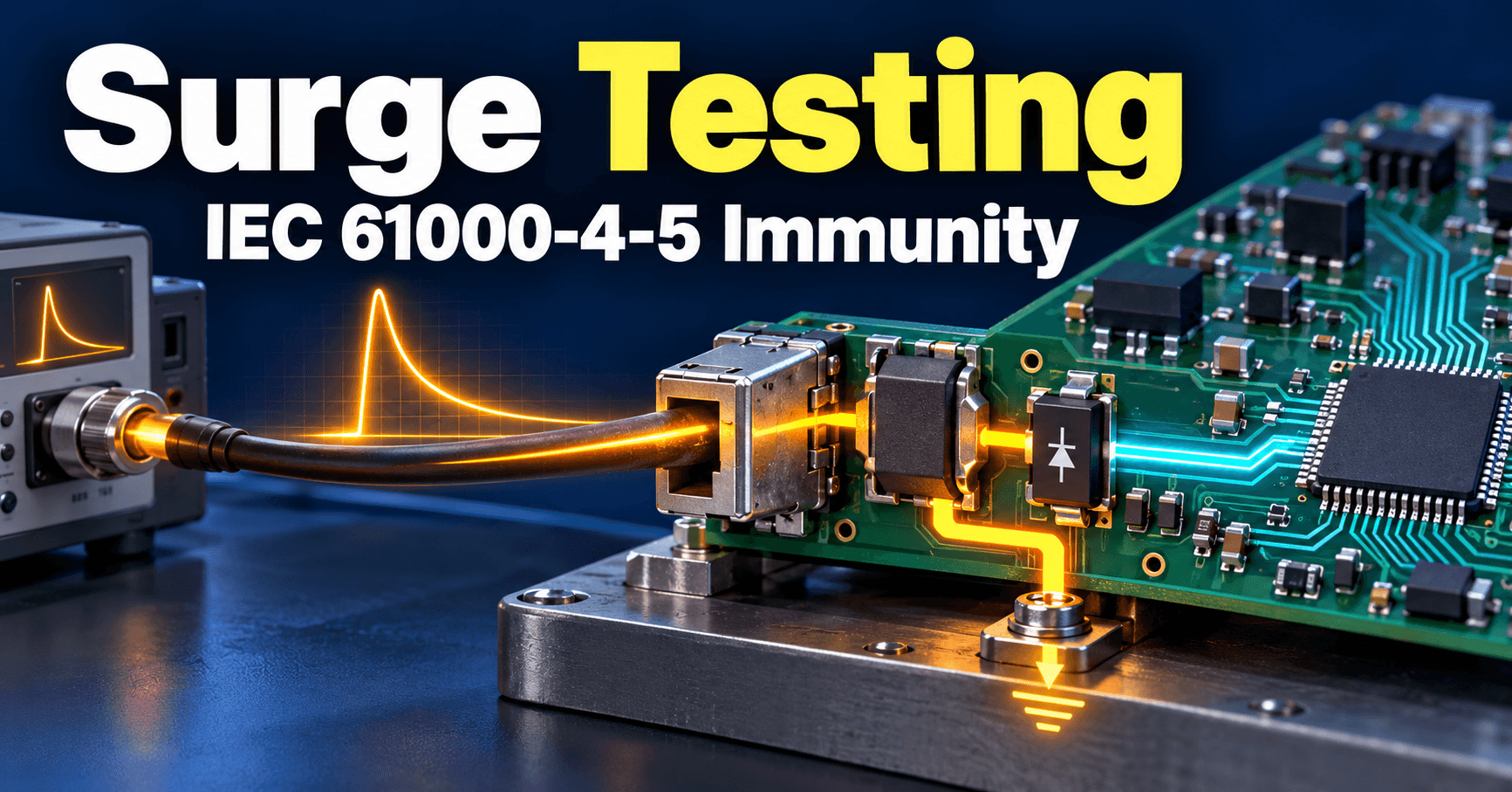
The surge generator is a combination wave generator (CWG): a charged capacitor discharges through a pulse-shaping RLC network into coupling/decoupling networks (CDNs) that connect to the equipment under test. Decoupling networks on the supply side prevent the surge from propagating back into the lab's mains distribution while coupling capacitors or gas discharge tubes inject the pulse onto the port under test. The generator's output impedance, not the EUT, largely determines the waveform actually delivered.
The 1.2/50 µs Voltage and 8/20 µs Current Waveforms
Why 1.2/50: rise time and decay time definitions
Into an open circuit, the CWG produces a 1.2/50 µs voltage waveform: front time of 1.2 µs (defined per IEC methodology from 30%–90% crossing points, scaled to an equivalent 10%–90% virtual origin) and a 50 µs time to half-value on the decay. This waveform represents the open-circuit voltage a lightning-induced surge would present to a high-impedance load — it's a standardized stand-in for the real, highly variable waveshapes seen in the field.
Why 8/20 µs current waveform and energy content
When the CWG output is shorted, the same generator produces an 8/20 µs current waveform — 8 µs front time, 20 µs to half-value. This is the waveform the generator delivers into a low-impedance load. Both waveforms come from the same physical generator and the same event; which one you observe depends on the impedance of what you connect it to. The combination wave generator is explicitly named for producing this combination: open-circuit voltage follows 1.2/50, short-circuit current follows 8/20.
Waveform parameters: peak voltage, source impedance, repeatability
The CWG's effective output impedance is standardized at 2 Ω, derived from the ratio of open-circuit peak voltage to short-circuit peak current (e.g., a generator producing 1 kV open-circuit and 500 A short-circuit implies 2 Ω). This is the same current-divider and voltage-divider arithmetic covered in Voltage Divider and Current Divider Rules — the voltage your EUT actually sees is set by the generator's source impedance in series with the CDN and in parallel with your protection device's clamping impedance. Repeatability tolerances on amplitude and timing are specified in the standard; a lab's calibration record for the generator should show compliance before any test data is trusted.
Relationship between voltage and current waveforms
Because the generator has a fixed source impedance, a TVS diode or other clamping device loaded onto the line will reduce the voltage seen at the EUT below the open-circuit 1.2/50 value, while increasing the current drawn through the clamp toward the short-circuit 8/20 shape. Protection device selection must account for the actual current the 2 Ω source will drive through a low-impedance clamp, not just the open-circuit voltage rating of the test level.
Test Level Classification and Severity
Level 1 through Level 4 voltage ratings
IEC 61000-4-5 defines open-circuit test voltages at four standard severity levels, generally ranging from around 0.5 kV at Level 1 up to 4 kV at Level 4, with "X" reserved for a level specified by the product committee. Exact kV values, waveform tolerances, and the applicable level per port type are listed in the standard's test level table — consult the current edition rather than relying on recollection, since table structure (line-to-line vs. line-to-ground columns) has been refined across editions.
Differential-mode vs. common-mode test levels
Differential-mode (line-to-line) surges stress components directly in the signal or power path and are generally specified at lower voltages because the coupling impedance from an external surge source into a differential path is higher. Common-mode (line-to-ground) surges are typically specified at higher voltages because lightning-induced ground potential rise couples far more efficiently into a line-to-earth path. A product passing differential-mode testing can still fail common-mode testing if its isolation barrier or clamping-to-chassis path is inadequate.
Coupling via power supply vs. I/O lines
AC mains ports typically see the most severe test levels since they have the longest, most exposed cable runs. Signal and telecom ports are tested at levels appropriate to their expected installation environment — a short shielded cable between two co-located enclosures warrants a lower test level than an outdoor sensor cable run hundreds of meters across a facility.
How to select appropriate levels for your application
Level selection is driven by the applicable product-family standard and the installation category of the port (indoor, outdoor-short, outdoor-long, etc.), not by designer preference. Check the relevant product-family or generic standard for your market and equipment class, then confirm the specific levels and coupling modes required per port type.
Protection Strategies and Circuit Design
Transient suppression devices: clamping voltage and response time
TVS diodes offer fast response (sub-nanosecond) and well-defined clamping voltage but limited peak power handling relative to their size. Gas discharge tubes (GDTs) handle very high surge currents cheaply but have slower response times and a let-through voltage spike before ignition — often requiring a coordinated two-stage design with a fast clamp downstream. Metal oxide varistors sit between these in speed and power handling but degrade with repeated surge exposure, shifting clamping voltage over device lifetime.
Filtering and decoupling to absorb surge energy
A series impedance — a resistor, ferrite, or small inductor — between a first-stage GDT and a second-stage TVS lets the GDT ignite and carry the bulk of the current while the series element limits the current into the faster, lower-power downstream clamp. This coordination is essential: without it, the TVS may see the full surge current and fail before the GDT ignites.
PCB layout techniques to minimize coupled paths
Keep the surge current path short and direct: protection devices should connect to the connector pin and ground/chassis reference with minimal trace length, avoiding routing the high-current return through sensitive ground planes shared with analog or digital logic. Via and pad sizing on the current-carrying path matters too — an undersized annular ring on a protection device's ground via can fail mechanically or electrically under repeated high-current surge pulses, which is one more reason the via geometry guidance in Annular Ring: IPC-6012 Minimum Ring Requirement applies even outside of pure reliability concerns.
Coordination between multiple protection layers
Multi-stage protection only works if each stage's clamping voltage, response time, and current capacity are coordinated against the others — a fast, low-current downstream device placed too close electrically to a slow upstream device can see the surge rise before the upstream device turns on.
Test Setup, Pass/Fail Criteria, and Documentation
Pre-test and post-test functional verification
Before surge injection, verify and record baseline functional performance against the manufacturer's defined performance criteria — every monitored function, communication interface, and output state. Repeat the same functional check after each surge application to detect both immediate and latent damage.
Measuring device response during surge injection
During injection, monitor the EUT for state changes, output glitches, or communication errors in real time where possible, since some failures (brief resets, momentary relay chatter) are not visible in a post-test-only check.
Pass criteria: no latchup, no permanent damage, no unwanted resets
Performance criteria are generally grouped into categories: normal operation during and after the test, temporary degradation that self-recovers, and loss of function requiring operator intervention — with permanent damage or unsafe operation never acceptable regardless of category. The applicable category per port and function must be defined in the test plan before testing begins, not decided after seeing results.
Recording test data and certification requirements
Documentation should include generator calibration status, waveform parameters actually applied, coupling network configuration, number of pulses and polarity, EUT configuration and cable lengths, and pass/fail results per port and per level — sufficient detail for another lab to reproduce the test.
Common Design Pitfalls and Lessons Learned
Undersizing protection components for surge energy
A TVS rated for the open-circuit test voltage but not for the actual peak power dissipated during the pulse width will fail silently in the field after a few events, even though it passed the lab test once.
Overlooking surge coupling paths on multi-layer boards
Surge current injected on one port can couple capacitively or inductively into adjacent traces and planes on a dense multi-layer board, appearing as a disturbance on a circuit that was never directly connected to the tested port.
Inadequate grounding return paths for surge current
If the chassis or earth return path for the protection device has significant inductance or a poor connection, the voltage developed across that return impedance during the current pulse adds directly to the voltage seen by downstream circuitry — sometimes exceeding what the clamp alone would suggest.
Interaction between surge protection and signal integrity
High-capacitance TVS devices placed on high-speed signal lines for surge protection can degrade eye diagrams or rise times; the trade-off between clamping speed/capacitance and signal bandwidth must be evaluated per interface, not assumed to be free.
Learning
Sign in to track your progress.
Evidence
Public projects engineers linked to Surge Immunity: IEC 61000-4-5 Waveform and Level.
No engineer has linked a project to this topic yet. Built something that proves it? Add the project and tag it with pcb-and-surge-immunity-iec-61000-4-5-waveform-and-level — it then shows here and on your public profile.