
Body Temperature: IR Thermopile Circuit
Learn how IR thermopile circuits extract microvolt body temperature signals through amplification, cold-junction compensation, and calibration.
Contents & prerequisites
Thermopile Sensor Fundamentals
Seebeck Effect and Voltage Generation
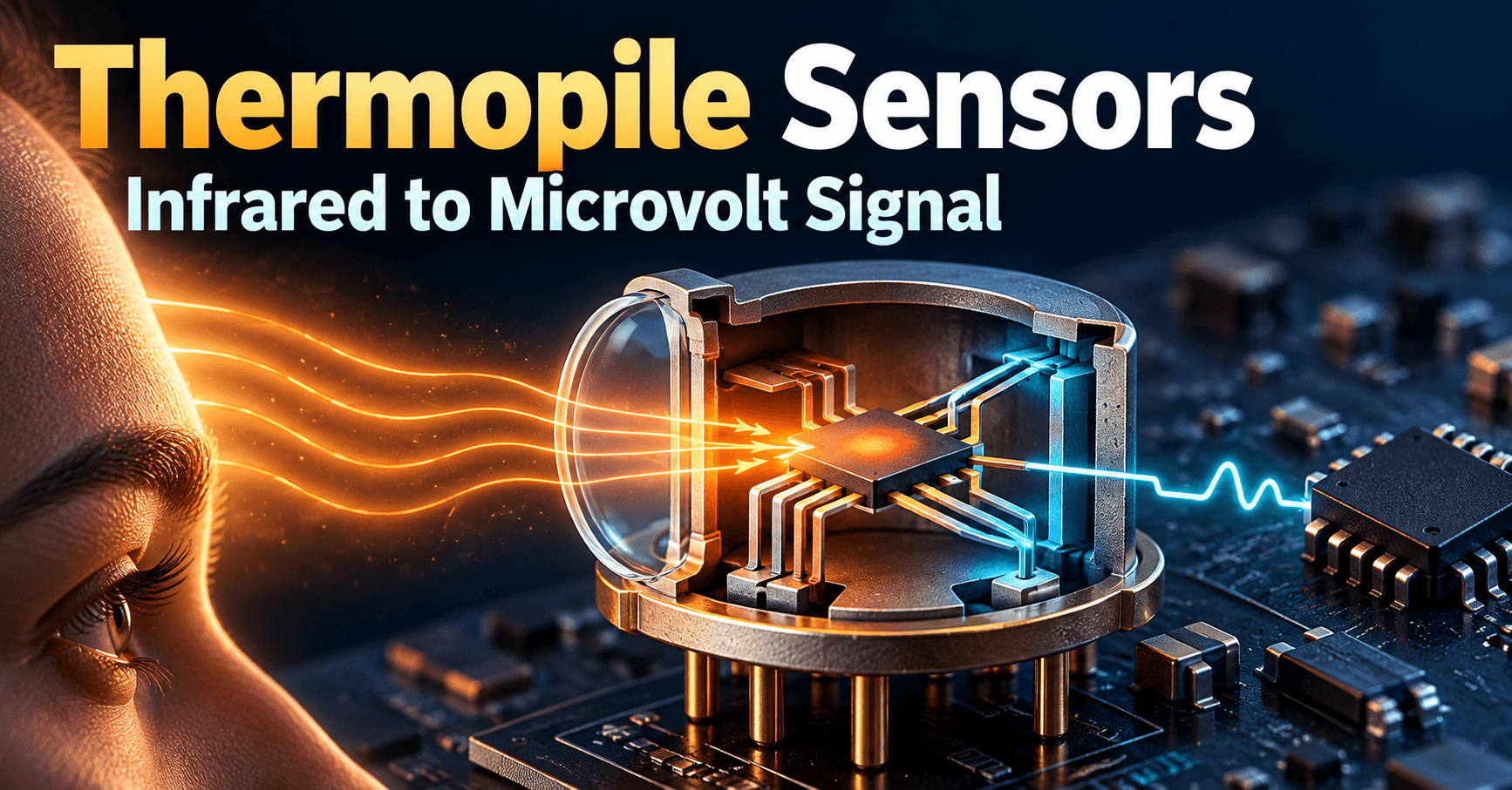
A thermopile converts infrared radiation into a measurable voltage through the Seebeck effect: when two dissimilar conductors form a junction and that junction sits at a different temperature than a reference junction, a voltage appears across the open ends. The magnitude depends on the Seebeck coefficients of the two materials and the temperature differential, typically expressed as microvolts per kelvin (µV/K) for a single junction pair.
For body temperature sensing, the "hot" junction is a thin absorbing membrane exposed to infrared radiation from skin (roughly 3–15 µm wavelength for the 30–42°C range of interest), while the "cold" junction sits on the sensor's substrate, thermally anchored to the package. A single junction pair generates only a few microvolts per degree of temperature difference — far too small to digitize directly with any practical ADC without amplification, which is why every thermopile front end needs a dedicated gain stage before conversion.
Thermopile Architecture: Series-Connected Thermocouple Junctions
Practical thermopile sensors stack dozens to hundreds of thermocouple junctions in series on a micromachined membrane, multiplying the per-junction Seebeck voltage by the junction count. A sensor with 100 junctions and a per-junction coefficient of 0.1 µV/K might produce 10 µV/K of net responsivity referenced to the target-to-ambient temperature difference, though actual responsivity specs are given in V/W or mV per degree in the component datasheet and should be read directly from that document rather than estimated. The series architecture also raises source impedance — often tens of kilohms — which has direct consequences for amplifier input bias current and noise, covered below.
Reference Junction Temperature Compensation
Because the thermopile output represents a difference between the hot (target) and cold (reference) junction temperatures, the absolute target temperature cannot be derived from the thermopile signal alone. The cold junction's actual temperature must be measured independently and added back into the calculation. This is cold-junction compensation, and skipping it is the single most common source of gross error in homebrew IR temperature designs — a sensor reporting a perfectly stable differential voltage will report a completely wrong absolute temperature if the package warms up by even 2–3°C due to nearby electronics or skin contact with housing.
Sensitivity and Output Range Characteristics
For non-contact body temperature measurement over the clinically relevant 34–42°C range, total thermopile output usually spans only tens to a few hundred microvolts across that entire span, depending on the sensor's field of view and the emissivity assumed for skin. This narrow dynamic range means the signal chain's noise floor, offset drift, and common-mode rejection all directly limit achievable clinical resolution — a 0.1°C resolution target may require resolving signal changes on the order of 1 µV or less, which drives most of the design decisions in the next section.
Signal Conditioning for Micro-Voltage Outputs
Instrumentation Amplifier Stage Design
The first active stage after the thermopile must be a true instrumentation amplifier (in-amp) topology, not a simple single op-amp difference amplifier, because the thermopile's high and matched-but-not-identical source impedances on each output pin make common single-op-amp dividers sensitive to impedance mismatch errors. A three-op-amp in-amp architecture — two buffering input stages followed by a difference amplifier — gives high input impedance on both inputs independently, which is essential when source impedance is in the tens of kilohms range. Readers building a discrete front end rather than using an integrated in-amp IC should review Two-Stage Op-Amp: Differential Input + Common-Source Output for the gain-and-offset trade-offs inherent in cascading an input differential stage with a single-ended output driver.
Common-Mode Rejection and Input Impedance Requirements
Thermopile outputs ride on a common-mode voltage set by the sensor's internal bias network, and any CMRR deficiency in the first stage translates directly into apparent temperature error, since common-mode drift (from supply noise or ambient temperature shifts) is indistinguishable from the differential signal after insufficient rejection. Target CMRR of 100 dB or better at DC and low frequency (thermopile signals are essentially DC to a few Hz). Input bias current matters too: with 20–50 kΩ source impedance, a bias current of 10 nA already produces hundreds of microvolts of offset error if the two input bias currents are unequal — favor amplifiers with FET or chopper-stabilized inputs over bipolar-input parts.
Low-Noise Preamplifier Topology
Because signals of interest can be a single microvolt, the preamp's input-referred noise density should be under roughly 20 nV/√Hz, and a chopper or auto-zero amplifier is usually preferred over a conventional low-offset bipolar op-amp because thermopile signals are near-DC — chopper stabilization removes 1/f noise and offset drift that would otherwise dominate the error budget. Gain is typically split: a first stage gain of 100–1000 close to the sensor to raise the signal above downstream noise, followed by a second gain/filter stage. When sizing the gain-setting resistor network, treat it as a simple potential divider problem — the Voltage Divider and Current Divider Rules apply directly to setting in-amp gain resistors and to modeling the loading effect of the ADC input stage on the preamp output.
Filtering and Bandwidth Optimization for Temperature Signals
Body temperature changes slowly, so the signal chain bandwidth should be aggressively limited — typically a low-pass corner between 1 Hz and 10 Hz is sufficient to track physiological temperature changes while rejecting wideband noise and 50/60 Hz mains pickup. A second-order Sallen-Key or multiple-feedback low-pass after the preamp, combined with a notch or sufficient rolloff at the local mains frequency, is standard practice. Oversampling in the ADC stage with digital averaging can further reduce the effective noise floor without adding analog complexity.
Reference Temperature Measurement
Thermistor or RTD Integration for Cold-Junction Compensation
A negative-temperature-coefficient (NTC) thermistor or a thin-film RTD mounted in thermal contact with the thermopile package provides the cold-junction reading. NTC thermistors are common in low-cost designs for their large resistance swing (easing ADC resolution requirements), while RTDs offer better long-term stability and linearity in higher-accuracy clinical designs. The thermistor's own nonlinear resistance-temperature curve must be linearized in firmware, usually via the Steinhart-Hart equation or a lookup table generated from the thermistor's resistance table.
Precision Analog-to-Digital Conversion
Both the amplified thermopile signal and the reference-junction temperature need conversion with enough resolution to support the target accuracy. For 0.1°C resolution across a ~10°C clinically relevant span with microvolt-level sensitivity, an ADC of 16–24 bits (delta-sigma types are common for their noise performance at low bandwidth) is typically needed on the thermopile channel. Note that the thermopile amplifier's output impedance and any residual mismatch look like a two-port network interacting with the ADC's input sampling capacitor; for designs where settling time or loading error becomes measurable, applying Two-Port Network Parameters: Z, Y, H, ABCD analysis clarifies how source and load impedances interact across the interface.
Calibration Methods: Single-Point vs. Multi-Point
Single-point calibration (adjusting a single offset against a known blackbody or calibrated reference at one temperature) corrects gross offset but leaves gain and nonlinearity errors uncorrected across the range. Multi-point calibration — typically three to five calibration temperatures spanning 34–42°C against a traceable reference — characterizes both offset and gain, and allows a polynomial or piecewise-linear correction curve to be stored per unit in production. Clinical-grade designs generally require multi-point calibration; consult the applicable regulatory guidance document (e.g., the relevant national standard for infrared thermometers) for required calibration point counts.
Temperature Linearization Algorithms
The relationship between thermopile output voltage and the fourth-power radiant temperature difference (from the Stefan-Boltzmann relationship) is nonlinear, so firmware must apply a function — often a polynomial fit or a lookup table derived during calibration — that converts corrected voltage plus cold-junction temperature into target temperature. A simplified correction loop looks like:
v_diff = read_thermopile_adc() * gain_cal
t_ref  = thermistor_to_celsius(read_ref_adc())
t_obj4 = t_ref_kelvin^4 + (v_diff / sensitivity_coeff)
t_obj  = fourth_root(t_obj4) - 273.15
t_obj_corrected = apply_emissivity_correction(t_obj, emissivity_skin)
The sensitivity_coeff and emissivity correction factor come from the calibration dataset, not from a generic datasheet constant, since optical path losses (window, lens) shift the effective sensitivity per unit.
Optical Path and Housing Design
Lens and Field-of-View Considerations
The lens (commonly a Fresnel or aspheric silicon lens) defines the field of view and determines how much of the detector's solid angle is actually filled by the forehead or tympanic target versus background. A field of view mismatched to the target area lets ambient background radiation leak into the measurement, producing systematic underestimation when the subject is farther from the sensor than intended.
IR Window Material Selection
Window materials must pass the 3–15 µm thermal IR band with minimal absorption — silicon, germanium, or specialized IR-transmissive polymers are typical choices, each with trade-offs in cost, mechanical durability, and transmission flatness across the band. Any absorption in the window itself heats the window and re-radiates, adding an error term that scales with window temperature — a second-order effect that calibration must account for if the housing is exposed to variable ambient conditions.
Thermal Shielding and Ambient Rejection
The thermopile cold junction must be thermally isolated from heat sources inside the device (battery, regulators, display backlight) to prevent reference-temperature drift that masquerades as target temperature drift. Physical shielding, thermally conductive paths to a stable mass, and keeping the thermistor close to the actual cold junction rather than elsewhere on the PCB are standard mitigations.
Distance-to-Spot Ratio and Non-Contact Range
The distance-to-spot (D:S) ratio defines how large an area is measured at a given standoff distance; a typical forehead thermometer might specify a D:S ratio around 5:1 to 10:1, meaning at 5 cm the spot diameter is roughly 0.5–1 cm. Operating outside the specified distance range causes the measured spot to include background (hair, air) rather than pure skin, introducing error that no amount of electrical calibration can correct — this is a mechanical/optical constraint that must be enforced by product design (e.g., a contact guide or proximity sensor) rather than firmware.
Analog Front-End Integration
Dual-Channel AFE Architecture: Signal + Reference
Many commercial thermopile AFE ICs integrate both the thermopile amplifier chain and the thermistor/RTD conversion channel on a single die, synchronizing both conversions so the cold-junction reading and the thermopile reading represent the same instant — important because thermal transients (e.g., a device just powered on and still warming) otherwise create a timing-skew error between the two channels.
Power Budget and Low-Power Operation Modes
Wearable or handheld battery-powered designs must budget for the thermopile AFE's duty cycle rather than running it continuously. Chopper-stabilized amplifiers draw more current than simple op-amps, and delta-sigma ADCs scale power with resolution and sample rate — a typical strategy is to run the AFE in a low-power standby state and wake it for a burst of samples (e.g., 1–2 seconds of averaging) only when a measurement is triggered, rather than continuously sampling. Total current budget figures (µA in standby, mA during active conversion) should be taken from the specific AFE and ADC datasheets being used, since they vary significantly between parts.
ADC Resolution and Sampling Rate Trade-offs
Higher ADC resolution and oversampling ratios reduce noise but increase conversion time and power draw — a delta-sigma converter running at a slow output data rate with high oversampling gives excellent noise performance for the near-DC thermopile signal but may add tens to hundreds of milliseconds of latency per reading, which is usually acceptable for a thermometer but must be budgeted into the overall measurement cycle time.
Digital Output Formats and Thermal Drift Correction
Firmware should timestamp and correct each reading using the simultaneous cold-junction value as described earlier, and ideally track the AFE's own die temperature (if available) to correct for amplifier offset drift with temperature — gain and offset drift coefficients from the AFE datasheet, applied as a function of measured ambient or die temperature, form the final correction stage before reporting a calibrated temperature value over the digital interface (I²C/SPI).
Medical Device Compliance and Accuracy
Measurement Accuracy Targets for Clinical Use
Clinical non-contact thermometers typically target accuracy within ±0.2°C to ±0.3°C across the clinically relevant range, per the applicable national or international standard for infrared clinical thermometers — consult that standard directly for the exact accuracy, repeatability, and test protocol requirements applicable to the target market, since they vary by region and device classification.
Emissivity Effects and Skin Reflectivity Compensation
Human skin emissivity is commonly assumed to be around 0.98, but variation due to moisture, cosmetics, or skin condition introduces error because the sensor cannot distinguish emitted radiation from reflected ambient radiation. A fixed emissivity constant is usually applied in firmware (as shown in the linearization pseudocode above), and some designs add an ambient-reflection compensation term using the housing or ambient temperature sensor to estimate reflected background contribution — but no digital correction can fully recover accuracy lost to grossly wrong emissivity assumptions, so the assumed value must be validated against the actual target population during characterization.
Temporal Stability and Drift Mitigation
Long-term drift comes from thermopile aging, amplifier offset drift, and thermistor self-heating or aging. Periodic self-calibration against a known internal reference (a stable on-board blackbody reference or shutter mechanism, where the housing design permits) helps bound drift between factory calibrations; absent that, specify and test drift over the device's expected service life against the applicable standard's stability requirements.
Environmental Factors: Ambient Temperature, Humidity, Airflow
Ambient temperature swings affect both the cold-junction reading and the optical path (window heating), humidity can affect IR transmission at the margins of the passband, and airflow across the sensor housing can create transient cold-junction gradients that corrupt a single-shot reading. Multi-sample averaging with outlier rejection, combined with requiring thermal settling time after device power-up or after moving between environments, mitigates most of these effects in practice — and matching the input protection network's leakage characteristics to the measurement's microvolt-level sensitivity is also worth checking, since Reverse Bias: Leakage Current, Breakdown Mechanisms explains how ESD diode leakage at the amplifier input can itself become a measurable offset source at these signal levels.
Learning
Sign in to track your progress.
Evidence
Public projects engineers linked to Body Temperature: IR Thermopile Circuit.
No engineer has linked a project to this topic yet. Built something that proves it? Add the project and tag it with biomedical-med-body-temperature-ir-thermopile-circuit — it then shows here and on your public profile.