
Static Timing Analysis (STA): PrimeTime / Tempus
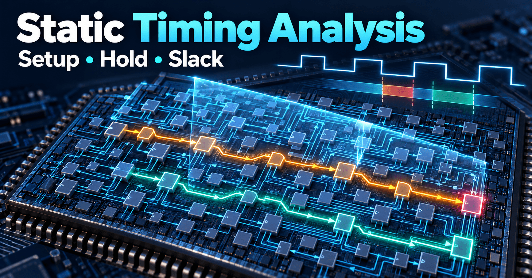
Static timing analysis compared across PrimeTime and Tempus: Liberty corners, setup/hold detection, clock skew, SDC exceptions, and ECO closure.
Contents & prerequisites
What is Static Timing Analysis?
Definition and role in the design flow
Static timing analysis (STA) is the process of verifying that every timing path in a digital design meets its required speed and stability constraints without simulating any input vectors. Instead of applying stimulus and watching waveforms, an STA tool walks the entire timing graph of a netlist — every cell, every net, every clock edge — and computes arrival and required times algebraically. It is the sign-off gate between synthesis/place-and-route and tapeout: no chip goes to a foundry without a clean STA report.
Why STA replaces dynamic simulation at sign-off
RTL simulation and gate-level simulation (GLS) tell you whether a design behaves correctly for the specific vectors you wrote. They do not tell you whether a path is fast enough, because simulation timing depends on whatever delay annotation (SDF) you loaded and only exercises the toggles present in your testbench. A single missed corner case — a rarely-toggled reset recovery path, an obscure multiplexer select — can hide a violation indefinitely. STA instead treats the netlist as a graph and computes delay along every arc using Liberty timing models, independent of whether any testbench ever activates that arc. This is why sign-off STA, not GLS, is the final authority on speed.
Exhaustive path coverage vs. test-vector limitations
A modern SoC can contain tens of millions of timing arcs. Simulation-based coverage of that space is statistically impossible — you'd need a test vector set that toggles every combination of path-enabling conditions. STA instead propagates symbolically: it assumes every path is potentially active unless you explicitly tell it otherwise (via false-path or case-analysis constraints). This exhaustiveness is STA's core value proposition, and also its core risk — if you under-constrain, the tool reports violations on paths that can never actually occur in silicon; if you over-constrain, it silently ignores paths that can.
Timing Models and Liberty Characterization
Cell delay and slew models from foundries
Every standard cell and macro is characterized by the foundry (or IP vendor) into a Liberty (.lib) file. Each timing arc stores delay and output slew as a function of input slew and output load, typically in a non-linear delay model (NLDM) lookup table, or as current-source models (CCS/ECSM) for higher accuracy at advanced nodes. STA tools interpolate these tables at runtime for the actual slew/load seen in your design.
Interconnect delay: RC trees and Elmore delay
Beyond the cell itself, the wire connecting it to its fanout has resistance and capacitance extracted post-route (SPEF/DSPF). STA reduces this RC network to an effective delay using Elmore-delay approximations or more rigorous AWE/model-order-reduction techniques, then re-characterizes the driving cell against that reduced load. Interconnect delay dominates total path delay at modern nodes, often exceeding cell delay on long routes, which is why STA accuracy is only as good as the parasitic extraction feeding it.
Temperature, voltage, and process corner variations
Delay is not a single number — it shifts with process (fast/slow transistors), voltage (IR-drop and supply variation), and temperature (mobility and threshold shifts). A design is signed off across a matrix of PVT corners: typically a slow corner for setup (worst-case max delay) and a fast corner for hold (worst-case min delay), plus intermediate corners for specific failure modes like SSG or FFG depending on foundry naming. Skipping a corner is a common root cause of silicon that works on the bench but fails in the field.
De-rating and derate factors
Even within one corner, STA applies derating factors (AOCV/POCV — advanced/parametric on-chip variation) to account for local, statistical variation between adjacent cells that a single global corner can't capture. Early-mode derates inflate hold-check delays downward and late-mode derates inflate setup-check delays upward, tightening margin further. Getting derate tables wrong is a frequent source of either false violations (over-pessimism, wasted area/power fixing non-problems) or missed violations (silicon fails).
PrimeTime Fundamentals
Architecture and analysis engine
Synopsys PrimeTime builds a timing graph from the gate-level netlist, SDC constraints, Liberty models, and parasitics, then performs graph-based analysis (GBA) by default, with path-based analysis (PBA) available for signoff-accurate re-verification of the worst paths that GBA flags.
Graph-based timing propagation
GBA computes delay through each node independently using worst-case slew merging at fanout points — fast, conservative, and suitable for full-chip runs with millions of paths. PBA re-derives the exact slew propagated along one specific path, recovering pessimism that GBA introduces (often 5-15% of path delay), at the cost of much higher runtime per path. The standard flow is GBA for the full design, PBA for the handful of paths closest to failing.
Endpoint classification: setup, hold, recovery, removal
A setup violation means data arrives too late relative to the capturing clock edge — the path is too slow. A hold violation means data arrives too early and corrupts the previous capture — the path is too fast relative to clock skew. STA detects both by computing, at every register or latch endpoint, the data arrival time versus the required time (derived from the clock edge, minus setup/hold margin, library uncertainty, and clock skew); negative slack in either direction is a violation. Asynchronous set/reset pins have analogous recovery (data-equivalent of setup) and removal (data-equivalent of hold) checks relative to the clock.
Multi-corner and multi-mode analysis
Real designs ship with multiple functional modes (test, scan, low-power, functional) each with its own clock frequencies and constraints, crossed against multiple PVT corners. PrimeTime's MMMC (multi-mode multi-corner) flow evaluates all mode/corner combinations in one session, reporting the worst slack per endpoint across the full matrix — because a path that's safe at one corner/mode may be the worst offender at another.
Tempus and Advanced STA Techniques
Tempus as PrimeTime's next-generation alternative
Cadence Tempus is architected for the same sign-off-quality STA but built around distributed, multi-threaded analysis from the ground up, targeting the same Liberty/SDC/SPEF inputs so designs can, in principle, move between PrimeTime and Tempus flows with the same constraint set. The practical differentiator tends to be runtime scalability on very large hierarchical blocks and tighter native integration with Cadence's place-and-route (Innovus) for in-design timing signoff.
Hierarchical and distributed analysis
Both tools support hierarchical STA — timing block-level partitions independently and stitching interface timing via extracted timing models (ETM/ILM) — but Tempus emphasizes distributed multi-machine analysis as a first-class flow, letting full-chip signoff runs partition across compute farms with less manual setup than PrimeTime's distributed processing option historically required.
Incremental timing updates for ECO iterations
After an engineering change — a buffer swap, a gate resize — re-running full-chip STA from scratch is wasteful. Both tools support incremental analysis: only the timing graph fan-in/fan-out of the changed cells is re-propagated, turning a multi-hour signoff run into a minutes-long update. This incremental engine is what makes iterative ECO convergence practical late in the schedule.
Machine learning-assisted slack prediction and bottleneck detection
Newer Tempus releases incorporate ML models trained on historical placement/routing data to predict post-route slack during early STA passes, flagging likely-critical paths before parasitics are even final, and clustering systematic bottlenecks (a clock-tree region, a congested macro boundary) rather than reporting thousands of individually-failing paths. PrimeTime has comparable predictive/ECO-guidance features under its own branding; check the current Synopsys documentation for the exact feature name and supported flow version before committing a methodology to it.
Critical Path Analysis and Slack Calculation
Forward and backward propagation of arrival times
STA computes arrival time by forward-propagating from each clock source and primary input, summing cell and net delay along every arc to each endpoint. Required time is computed backward from each endpoint's capturing clock edge, subtracting setup margin and adding/subtracting clock latency and uncertainty.
Required time computation and slack metrics
Slack = required time − arrival time for setup checks (must be ≥ 0), and arrival time − required time for hold checks. A worked simplified example: a register launches data at a rising clock edge at t=0, the combinational path has 1.8 ns of cell+net delay, the clock period is 2.0 ns, and setup time at the endpoint is 0.15 ns. Required time = 2.0 − 0.15 = 1.85 ns. Arrival time = 1.8 ns. Setup slack = 1.85 − 1.8 = 0.05 ns — a passing but thin margin.
Timing criticality and margin budgeting
Design teams typically budget margin across clock uncertainty, OCV derating, and a guardband for late ECOs, so that the "real" slack available for logic design is less than the nominal period. A path reporting +0.05 ns slack at signoff with no further margin is a red flag for any post-signoff metal fix.
Report generation: worst negative slack (WNS) and total negative slack (TNS)
WNS is the single worst (most negative) slack value in the design — the one path furthest from meeting timing. TNS sums all negative slacks across all failing endpoints, capturing the breadth of the problem, not just its depth. A design with WNS of −20 ps but TNS of −50 ns has thousands of marginally-failing paths, a very different fix strategy (global buffering/VT swap) than a single path at −20 ps (local resize).
Handling Clock Distribution and Skew
Ideal and propagated clock modes
Early in the flow, before clock tree synthesis, STA runs in ideal clock mode: zero latency, zero skew, a convenient fiction for early logic-synthesis timing closure. Post-CTS, propagated clock mode is mandatory — actual buffer and wire delay through the clock network is included, revealing real skew between launch and capture registers.
Generated and divided clocks
Divided or gated clocks (half-rate, generated from a PLL output through a divider) must be declared via create_generated_clock in SDC so STA understands the relationship to the master clock; failing to declare this correctly causes STA to treat the generated clock as asynchronous, either masking real paths or flagging false violations across the whole clock domain.
Clock network latency and skew impact on setup/hold
Positive skew (capture clock arrives later than launch clock) helps setup timing but hurts hold timing, and vice versa. Jitter — cycle-to-cycle clock period variation from the PLL/clock source — is modeled as an additional uncertainty term subtracted from setup margin and added to hold margin, since STA is a static analysis and cannot itself simulate jitter's time-domain randomness.
Interaction with Clock Tree Synthesis (CTS) results
The skew and latency numbers STA uses post-route come directly from the clock tree built during Clock Tree Synthesis (CTS); a CTS run that deliberately introduces useful skew to fix a tight setup path will show up in STA as reduced setup slack at that endpoint and correspondingly reduced hold margin at its neighbor, so STA and CTS iterate against each other rather than running once in sequence.
Constraints, Exceptions, and Timing Closure Workflows
SDC (Synopsys Design Constraint) file structure
The SDC file is the contract between designer intent and the STA tool: clock definitions (create_clock), input/output delays (set_input_delay, set_output_delay), false paths, multi-cycle paths, and case analysis all live here. An incomplete or inconsistent SDC is the single most common cause of both missed silicon bugs and wasted engineering effort chasing phantom violations.
Port timing, datapath, and pipeline constraints
Primary I/O timing is constrained relative to the external clock at the chip boundary, specifying how much of the clock period is consumed by board-level delay before/after the chip's own logic. Pipeline constraints document the intended latency at each stage so that engineers reviewing the report can distinguish a true violation from a path that was always meant to borrow a cycle.
False paths, multi-cycle paths, and case analysis
A false path is a structurally valid timing path that will never actually propagate meaningful data — for example, a path through a configuration register set once at boot and never touched again, or a path between two clock domain crossing synchronizer stages that is handled by metastability settling time rather than single-cycle timing. These must be declared with set_false_path; otherwise STA will try to close timing on a path that doesn't need it, wasting area and power on unnecessary buffering. A multi-cycle path is a path intentionally allowed two or more clock cycles to settle (common in multipliers or deep datapaths), declared with set_multicycle_path; without this declaration STA enforces single-cycle timing on a path designed for multi-cycle operation, reporting a violation that isn't real. Case analysis (set_case_analysis) tells STA that a particular control pin is tied to a fixed value in a given mode, pruning paths that can't be active simultaneously with others — essential for scan-test and multi-mode designs where mode-select pins gate mutually exclusive logic.
Iterative closure with placement, routing, and buffer insertion
STA doesn't just report pass/fail — its per-path slack numbers directly drive placement and routing optimization. A path with negative setup slack tells the place-and-route tool where to insert buffers, upsize cells, or reroute nets to shorten delay; a path with negative hold slack tells it where to insert delay cells instead. This loop — place, route, extract parasitics, run STA, feed slack back to the optimizer — repeats across multiple iterations until WNS and TNS converge to zero (or an agreed margin) at every corner and mode.
ECO flow integration for last-mile fixes
After place-and-route is frozen, remaining violations are fixed through a metal-only or spare-cell ECO: STA identifies the exact failing paths, an ECO tool proposes minimal gate-level changes (cell swap, buffer insertion, net reroute), and incremental STA re-verifies only the affected fan-in/fan-out cone before the change is committed to the physical database — avoiding a full re-layout this late in the schedule.
Learning
Sign in to track your progress.
Evidence
Public projects engineers linked to Static Timing Analysis (STA): PrimeTime / Tempus.
No engineer has linked a project to this topic yet. Built something that proves it? Add the project and tag it with digital-electronics-static-timing-analysis-sta-primetime-tempus — it then shows here and on your public profile.