
Timing Closure: Critical Path, Register Retiming
Timing closure explained: find the critical path, apply register retiming, and use the right synthesis directives to pass STA on real FPGA silicon.
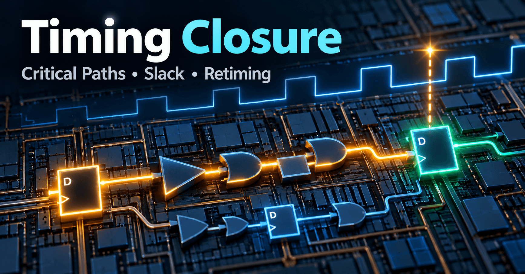
Contents & prerequisites
What Is Timing Closure and Why It Matters
Definition: meeting all timing constraints in a design
Timing closure is the state in which every register-to-register path in a synthesized and placed-and-routed design satisfies the setup and hold requirements imposed by its clock constraints. It is not a yes/no property of the RTL — it is a property of the final, placed netlist, after the tool has assigned real wire lengths, real buffer delays, and real routing congestion to every signal. A design that "meets timing" in a behavioral simulation (where every assignment appears to happen instantaneously on a clock edge) says nothing about whether the same design meets timing once it has been mapped onto actual LUTs, routing fabric, and I/O buffers.
Consequences of timing violations in production silicon
A simulation runs on an idealized zero-delay or unit-delay model. Real silicon has propagation delay through logic cells, resistance and capacitance in interconnect, and clock skew between the arrival times of the same clock edge at different flip-flops. If a path's total delay exceeds the clock period, the receiving register may sample a signal that is still transitioning — not glitching obviously, but metastable or simply wrong. This doesn't always crash the design outright. More insidiously, it produces intermittent, data-dependent, temperature- and voltage-sensitive failures: a design that passes bench testing at room temperature and fails in the field at the corner of the voltage/temperature envelope. Timing violations are a leading cause of "but it worked in the lab" bugs.
Relationship to clock frequency, power, and area trade-offs
Timing closure, power, and area are coupled. Pushing clock frequency higher shrinks the time budget for every path, forcing either faster (larger, more power-hungry) logic cells or shorter combinational chains — which usually means more pipeline registers, which costs area and adds dynamic power from additional clocked flip-flops. Conversely, accepting a lower frequency relaxes the whole design, often letting you remove pipeline stages and save both area and power. Every timing closure decision is implicitly a point on this frequency/power/area trade-off surface, and register retiming is one of the main levers for moving along that surface without touching the design's observable behavior.
Understanding the Critical Path
Definition and identification of critical paths in combinational logic
The critical path is the single register-to-register (or I/O-to-register, or register-to-I/O) path with the least timing margin — the path that determines the maximum achievable clock frequency for that clock domain. It's found by the static timing analyzer (STA) inside your place-and-route tool, not by eyeballing the RTL. The STA walks every timing arc in the netlist, sums propagation delays along every possible path, and reports the path(s) with the worst slack. You find your critical path by opening the timing report after implementation — in Vivado this is report_timing, in Quartus it's the Timing Analyzer's Slack report — and reading the worst setup path, which will list every cell and net delay contributing to the total.
How timing analyzers report slack (positive vs. negative)
Slack is the difference between the required arrival time (derived from the clock period and any input/output delay constraints) and the actual arrival time computed by the STA. Positive slack means the path has margin — the signal arrives before it's required. Negative slack means a timing violation: the signal would arrive too late to be reliably captured. A design isn't closed until every path's worst-case slack is ≥ 0 at the target clock frequency, across the specified process/voltage/temperature corners.
Multi-cycle and false paths: annotations and exceptions
Not every register-to-register path is meant to be covered in one clock cycle. A path that is only allowed to settle over two or more clock cycles (common in deliberately slow control logic) should be marked a multi-cycle path; a path that STA would analyze but that can never physically occur — because of mutually exclusive control signals, for example — should be marked a false path. Both are specified as timing constraint exceptions (SDC set_multicycle_path / set_false_path). Omitting these annotations forces the tool to over-optimize paths that don't need it, wasting area and effort, or worse, reporting spurious violations that mask real ones.
Critical path through memory blocks vs. LUT fabric
Timing behaves differently depending on what resource implements a path. A path through LUT fabric accumulates delay roughly linearly with logic depth and fanout; a path through a dedicated memory block has a fixed, often larger, read latency that doesn't scale with your logic at all. If you're deciding between inferring a RAM from an array declaration or explicitly instantiating a block RAM primitive, the timing implications differ — see BRAM Inference vs. Instantiation Trade-offs for how that choice affects both the critical path and resource usage. A common mistake is optimizing LUT logic around a memory read when the memory's own access time is actually the bottleneck.
Register Retiming Fundamentals
Principle: moving registers across combinational boundaries without changing logic
Retiming is the automated or manual relocation of registers across combinational logic boundaries such that the functional behavior of the circuit — its input/output relationship, cycle for cycle — is preserved, while the distribution of delay between registers changes. If a chain of combinational logic has 8 ns of delay sitting entirely before one register, retiming can split it into two 4 ns segments with a register inserted in between, doubling the achievable clock frequency for that chain at the cost of one extra cycle of latency.
Forward and backward retiming: moving registers toward outputs or inputs
Forward retiming pushes a register through a logic gate toward the output, absorbing the gate's delay onto the path after the register. Backward retiming pulls a register through a gate toward the input, absorbing the delay before it. The tool (or the engineer, doing it by hand) chooses direction based on which side of the gate has more slack to spend. Across a tree of gates with multiple fanout, this becomes a constraint-satisfaction problem, which is why most engineers lean on CAD automation rather than doing it node-by-node.
Retiming constraints: dependency preservation and feedback loops
Retiming must preserve data dependencies: a register cannot move past a node if doing so would change which values converge on which cycle for any downstream consumer, and it cannot move in a way that breaks a feedback loop's cycle count (an accumulator's feedback path, for instance, has a fixed number of registers that defines its sequential behavior — moving one without moving its pair changes the function). Combinational loops, asynchronous resets, and set/reset logic with asymmetric polarity are common blockers. Tools that perform retiming on RTL described with non-blocking assignments can track these dependencies reliably; code that mixes blocking and non-blocking assignment incorrectly can confuse a retiming engine's model of what's a register versus what's a wire — see Blocking (=) vs. Non-Blocking (<=) Assignment Rules for why that distinction matters structurally, not just stylistically.
Why retiming reduces combinational delay on critical paths
The core benefit is simple: shorter combinational segments between registers mean less delay per clock period, which means a higher achievable frequency for a fixed logic function. The total combinational work doesn't disappear — it's redistributed across more pipeline stages, each with less delay, which is why retiming trades latency (more cycles to get an answer) for throughput (a higher clock rate at which new inputs can be accepted).
Retiming Techniques and Implementation
Automatic retiming in CAD tools vs. manual hand retiming
Most FPGA synthesis tools offer automatic register retiming as a synthesis directive. It works well on datapath-style logic — adders, comparators, wide arithmetic chains — where the tool can clearly see register boundaries and combinational cones. It works less well across hierarchical module boundaries, memory interfaces, or logic with complex reset/enable structures, where the tool may conservatively refuse to move a register rather than risk a functional change. Manual retiming — physically rewriting the RTL to insert a pipeline register and adjust downstream logic — is still common for datapaths like a barrel shifter, where a wide shift network's delay is well understood and a designer can deliberately stage the shift across 2–3 clock cycles rather than hope automatic retiming finds the same split.
Pipeline balancing: distributing stages evenly across paths
When a design has multiple parallel paths feeding a common point — for example, several ALU operations feeding a result mux — adding a pipeline stage to only the slowest path doesn't help if a different path then becomes the new bottleneck. Pipeline balancing means distributing register stages so that every parallel branch has approximately equal delay before reconverging, which avoids wasting a cycle of latency on branches that didn't need it.
Retiming across hierarchical boundaries and module interfaces
Retiming inside a single flat module is well supported; retiming across a module boundary generally requires flattening the hierarchy for synthesis or explicitly enabling cross-boundary optimization, since many tools treat module ports as fixed timing boundaries by default. If your critical path crosses an instantiated submodule, check whether your synthesis tool's retiming pass is scoped to "this module only" or "whole design" — the default is often more conservative than you expect.
Effect of retiming on latency, throughput, and state initialization
Every inserted pipeline register adds one clock cycle of latency between input and output. For feed-forward datapaths this is usually free to absorb (the consumer just waits one more cycle). For designs with feedback — state machines, accumulators — adding a cycle of latency inside a feedback loop changes the loop's behavior, so retiming tools generally refuse to retime registers that participate in a loop unless the whole loop is moved consistently. Reset and initial-value behavior must also be re-verified: a newly inserted register needs its own reset and initial value chosen to match the function being replaced, or the one-time power-up behavior of the circuit changes even though its steady-state behavior doesn't.
Practical Timing Closure Strategies
Synthesis optimization: -fanout, -effort, -register_balancing directives
Synthesis tools expose directives that steer retiming and general optimization effort. In Vivado, -retiming and the register_balancing synthesis attribute enable the retimer; in Quartus, physical synthesis optimizations include register retiming under "Advanced Physical Synthesis." Effort-level settings (e.g., high-effort mapping) trade longer compile times for more aggressive restructuring, including deeper retiming search. Fanout control directives limit how many loads a single driver feeds before the tool inserts buffering, which indirectly affects where retiming candidates appear, since high-fanout nets are frequent critical-path contributors.
Floorplanning and placement-driven timing improvements
A logically short path can still fail timing if the two registers end up placed far apart on the die, because the net delay (wire delay) dominates over cell delay at that distance. Floorplanning — constraining critical logic to a physical region, or using pblocks/region constraints — reduces this risk by keeping tightly-coupled logic physically close. This matters especially after retiming inserts new registers: a register added purely to fix a timing equation needs to also land in a sane physical location, which is why timing closure is iterative between synthesis and placement, not a single synthesis-time decision.
Logic restructuring: breaking wide muxes, adding intermediate stages
Wide multiplexers — selecting among many sources — are common critical-path offenders because their logic depth grows with the log of the input count, and their fanout cone can be wide too. Breaking a wide mux into a tree of narrower muxes with a register between tree levels is a standard manual technique, functionally equivalent to automatic retiming but applied deliberately where the tool's search didn't find it. The same principle applies to wide arithmetic comparators and priority encoders.
Constraint specification: clock definition, input/output delays, false paths
None of the above matters if your constraints are wrong. A missing or incorrect create_clock, missing input/output delay constraints on I/O ports, or absent false-path exceptions on genuinely unrelated signals will cause the STA to either miss real violations or report phantom ones. Timing closure work should always start with an audit of the SDC file before touching any RTL.
Retiming Trade-offs and Side Effects
Latency increase: pipeline depth and dataflow implications
Every retiming pass that adds pipeline depth increases end-to-end latency. In a streaming datapath this is usually tolerable; in a tight feedback control loop (a PID controller updating every cycle, for instance) added latency can change the closed-loop dynamics of the system being controlled, which is a system-level concern, not just a timing one.
Area overhead: additional pipeline registers vs. timing gain
Each inserted register costs one flip-flop per bit of the pipelined signal. For a 128-bit datapath, adding one pipeline stage costs 128 flip-flops — usually cheap in LUT-fabric terms, but not free, and if retiming is applied aggressively across many stages the flip-flop count can become a real contributor to device utilization.
Power consumption: switching activity in longer pipelines
More registers toggling every cycle means more dynamic power, proportional to capacitance, voltage squared, and switching frequency. A deeply pipelined, high-frequency design will draw meaningfully more power than a shallow, lower-frequency equivalent doing the same aggregate work, which matters for thermally constrained or battery-powered systems.
Verification challenges: handling reset, initialization, and test modes
Added pipeline registers need correct reset behavior, and test or bypass modes (scan chains, built-in self-test) that assumed a particular latency may need updating. Functional simulation should be rerun after any retiming pass — automatic or manual — specifically checking reset recovery and the first few cycles after power-up, since retiming preserves steady-state behavior but can alter transient behavior.
Common Pitfalls and Debugging
Retiming failures: unmovable registers (I/O, special functions, asynchronous)
Some registers cannot be retimed: I/O registers physically located in the pad ring, registers with asynchronous set/reset tied to external events, registers feeding or fed by dedicated hard-IP functions (DSP blocks, transceivers) with fixed-latency interfaces. When the tool reports "register not retimed," check the synthesis log for the specific reason — it usually names the blocking attribute or structure directly.
Timing reports: interpreting path delay, net delay, and cell delay
A timing report breaks total path delay into cell delay (time through each logic element) and net delay (time on each wire). If net delay dominates, the fix is placement/floorplanning; if cell delay dominates, the fix is logic restructuring or retiming. Misreading which component dominates leads to solving the wrong problem — spending days restructuring logic when the real issue is routing congestion.
Post-implementation verification: static timing analysis (STA) vs. simulation
STA is exhaustive across all paths and corners but assumes your constraints are correct; simulation exercises actual functional behavior but only for the vectors you ran. Neither alone is sufficient — a design can pass STA with fully correct constraints and still fail functionally if the constraints themselves were wrong (an unconstrained false path that actually matters), and a design can simulate perfectly while violating timing because simulation doesn't model real delay.
Incremental improvements: when to retime vs. when to reduce frequency
If a single path is marginally negative (a few hundred picoseconds) after a reasonable retiming effort, further restructuring often yields diminishing returns relative to engineering time spent. In that case, the pragmatic choice is frequently to reduce the target clock frequency for that domain rather than chase the last few picoseconds through increasingly invasive pipeline changes — especially late in a project schedule where verification risk outweighs marginal frequency gain.
Learning
Sign in to track your progress.
Evidence
Public projects engineers linked to Timing Closure: Critical Path, Register Retiming.
No engineer has linked a project to this topic yet. Built something that proves it? Add the project and tag it with digital-electronics-timing-closure-critical-path-register-retiming — it then shows here and on your public profile.