
3D Model Assignment for Component
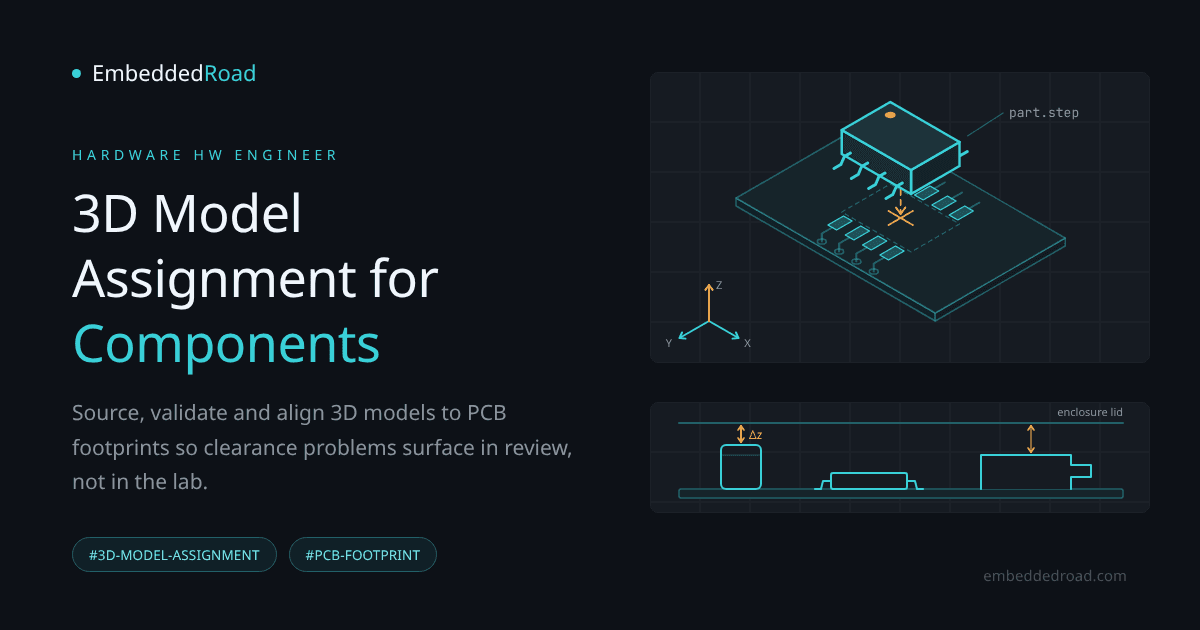
Assign and validate 3D component models to catch mechanical interference, height errors, and footprint misalignment before PCB fabrication.
Contents & prerequisites
Why 3D Models Matter in Component Design
A footprint in your PCB layout tool is an abstraction: pads, a silkscreen outline, maybe a courtyard rectangle. It tells you almost nothing about how tall a component is, where its connector shroud overhangs, or whether its body will clear the shield can two rows over. A 3D model closes that gap. It turns a 2D abstraction into a volumetric object that can be checked against every other volumetric object on the board, the enclosure, and the neighboring assemblies.
Role of 3D models in design validation
The 3D model is the bridge between electrical intent (schematic), physical placement (layout), and mechanical reality (enclosure, heatsink, connector mating). Without it, mechanical fit is verified only after boards come back from fab — at which point a connector that's 2 mm too tall means a respin, not a rework.
Mechanical clearance verification
Clearance checks answer questions layout rule checkers can't: does this electrolytic capacitor's can clear the chassis standoff? Does the USB-C connector's shell interfere with the adjacent inductor's shield? These are three-dimensional questions, and a correct model with accurate height and body geometry is the only way to answer them before fabrication.
Assembly simulation and collision detection
Modern ECAD tools can export the full board assembly — components in their 3D glory, in their placed positions — into MCAD. There, mechanical engineers check for collisions against the enclosure, bezels, cable assemblies, and other boards in a stack. This is the point where a hardware engineer's component selection decisions either get validated or get kicked back with a redline.
Documentation and manufacturing handoff
Assembly drawings, fabrication packets, and CM-facing documentation increasingly include 3D-derived views rather than hand-drawn ones. A correct 3D model means the step file you hand to a contract manufacturer actually represents what gets built, not an idealized sketch of it.
Understanding Component 3D Model Formats
STEP (.stp) and IGES (.igs) for CAD integration
STEP (ISO 10303-21) is the de facto standard for exchanging exact boundary-representation (B-rep) solid geometry between ECAD and MCAD. Use STEP whenever the model needs to survive a round-trip into SolidWorks, Creo, or similar — it preserves solid geometry, not just a visual shell. IGES is older and still circulates for legacy libraries, but it has known issues with surface stitching on complex parts (gaps between faces that cause "leaky" solids in some MCAD importers). If you're given a choice, always take STEP over IGES.
VRML and U3D for visualization
VRML (.wrl) and U3D are mesh-based formats carried over from an earlier generation of ECAD 3D viewers. They render color and shape for visual inspection inside the PCB tool but are not reliable for precision mechanical analysis — a VRML mesh approximates curves with flat facets, which can misrepresent true clearance by fractions of a millimeter depending on tessellation density. Treat VRML/U3D as "good enough to see it," not "good enough to measure it."
Model accuracy levels and detail requirements
Not every component needs a photorealistic model. A 0402 resistor can be a simple extruded box with correct height and footprint — nobody needs beveled termination edges for a clearance check. A board-to-board connector or an RF shield, on the other hand, needs accurate geometry because its true silhouette (keep-outs, latch tabs, overhangs) is exactly what you're checking against neighbors. Match model fidelity to the component's mechanical risk, not to aesthetics.
File size optimization for design tools
High-poly STEP models from some manufacturers can run tens of megabytes per part. A library with a few hundred such parts will noticeably slow 3D rendering and version control operations. Where your ECAD tool supports it, use simplified STEP exports (reduced body detail, no internal structure) for high-count passive parts, reserving full-detail models for connectors, mechanical hardware, and anything near an enclosure boundary.
Sourcing 3D Models for Components
Manufacturer-provided models and datasheets
The first and best source is the component manufacturer's own CAD model, usually downloadable from the product page alongside the datasheet. These models should be dimensionally derived from the same drawing that generated the datasheet's mechanical outline — cross-check the model's bounding box against the datasheet's envelope dimensions before trusting it.
Vendor libraries and online model repositories
Distributor-hosted libraries (the model repositories run by major distributors and ECAD vendors) are convenient but variable in quality — some are community-contributed and not verified against the current datasheet revision. Treat them as a starting point, not a final answer, especially for connectors and mechanical parts where a single millimeter of error changes everything downstream.
Working with approved component vendors
If you're already working from an approved vendor list, align 3D model sourcing with the same vendor relationships you use for part selection and substitution — see Alternative Component Cross-Reference for how substitute parts are qualified. A substitute part is only a true drop-in if its mechanical envelope matches as well as its electrical pinout; don't assume the 3D model of the original part is still valid for the replacement.
Validating model authenticity and dimensions
Before accepting any third-party model, measure it against the datasheet's mechanical drawing on at least three axes: overall length/width, height (including the tallest feature — connector latch, cap vent, shield tab), and pin/pad pitch. A model that's correct in X/Y but wrong in Z is still dangerous, since height errors are exactly what cause enclosure-lid interference discovered only at final assembly.
Assigning 3D Models to Footprints
Linking 3D models to component footprints
The 3D model attaches to the PCB footprint, not the schematic symbol — schematic symbols are purely logical. In most ECAD tools this is a property on the footprint: a file path or library reference plus a transform (offset, rotation, scale). This pairing should happen as part of footprint creation, following the same rigor discussed in Component Footprint Creation per IPC-7351 — a footprint built to spec but married to the wrong 3D model still produces a board that doesn't fit.
Coordinate system and origin placement
The model's origin must coincide with the footprint's origin (typically pin 1 or the part centroid, per your library convention) and its native coordinate plane must align with the board's top surface at Z=0. A model authored with its origin floating somewhere inside the body, rather than at the footprint reference point, will appear offset or embedded in the board when placed — a common and easy-to-miss error.
Rotation and offset configuration
Example: a connector's STEP model is authored with its mating face pointing along the model's native +X axis, but your footprint expects the mating face to point off the board edge along layout +Y. You'd apply a 90° Z-axis rotation in the footprint's 3D model properties:
Model: conn_xyz.stp
Offset X/Y/Z: 0.00 / 0.00 / 0.00 mm
Rotation X/Y/Z: 0 / 0 / 90 deg
Always verify visually after setting the transform — don't trust the numeric fields alone, since a sign error (90° vs. -90°) is indistinguishable from correct until you look at it from the side.
Library management and version control
Treat 3D model files as versioned library assets, not loose attachments. When a manufacturer revises a part's mechanical drawing (new package height, revised connector shell), the model needs to be re-validated and the library entry re-released with a version bump — otherwise designs pulling "latest" silently inherit stale geometry.
Design Validation Using 3D Models
Board stackup visualization
With accurate models assigned, you can render the full board stack — PCB substrate, tallest components, connectors — and check against enclosure Z-height budgets before layout is finalized, rather than finding out from a mechanical engineer that the board stack is 1.5 mm too thick.
Component-to-component spacing checks
3D clearance checks catch body-to-body interference that 2D courtyard rules miss: overhanging connector shells, angled electrolytic cap bodies, or tall inductors that lean into a neighbor's keep-out only in the Z axis.
Thermal management and airflow paths
Accurate component height and footprint also feed thermal simulation — heatsink contact area, airflow channel height above tall components, and clearance for thermal pads all depend on correct 3D geometry, not nominal datasheet numbers rounded for convenience.
Test point and connector accessibility
Before committing to layout, use the 3D view to confirm that test points and connectors remain accessible with the enclosure closed or with a bed-of-nails fixture — accessibility problems found in the lab after fabrication are expensive; the same check in 3D during layout is free.
Common Pitfalls and Best Practices
Model scale and unit consistency errors
The single most common failure: mixing inch-based and millimeter-based models in the same library without correcting the scale factor, producing a part that's 25.4x too large or too small. Always confirm units on import, and spot-check a known dimension against the datasheet immediately after assigning a new model.
Misalignment between 2D footprint and 3D model
A model that renders fine in isolation but is offset or rotated relative to its footprint will pass a casual visual check and still fail in assembly. Validate alignment by checking pin 1 position and mounting hole locations in the combined 3D view, not just the silhouette.
Outdated or unofficial models
Community-sourced models can lag behind a manufacturer's mechanical revision by years. Where mechanical risk is high — connectors, mounting hardware, anything touching an enclosure — prefer the manufacturer's current model over a cached third-party copy, even if it means more manual cleanup.
Documentation and traceability in manufacturing
Record which model version and source was used for each library part, the same way you'd track a datasheet revision. When a mechanical interference surfaces late in a program, the first question is "was the model current," and you want that answer in minutes, not days.
Integration with Design Tools and Workflow
CAD tool import and compatibility
Most ECAD tools import STEP/IGES directly into the footprint editor and export a combined board STEP for MCAD. Confirm your specific tool's handling of units and coordinate planes on import — some tools silently assume millimeters regardless of the file's embedded unit tag, which reintroduces the scale error described above.
Assembly drawings and manufacturing files
The same 3D assembly used for mechanical review can generate accurate assembly drawing views, reducing manual drafting and the risk of a hand-drawn view disagreeing with the actual placed geometry.
Communication with contract manufacturers
Sharing a STEP export of the fully populated board with your CM gives them an unambiguous reference for fixture design, panel spacing, and reflow oven clearance checks — far more reliable than a 2D assembly drawing alone, and it short-circuits a class of "that part doesn't fit our fixture" surprises discovered during first-article build.
Learning
Sign in to track your progress.
Evidence
Public projects engineers linked to 3D Model Assignment for Component.
No engineer has linked a project to this topic yet. Built something that proves it? Add the project and tag it with hardware-hw-3d-model-assignment-for-component — it then shows here and on your public profile.