
Load Cell: Types (Shear, Bending, Column), Rated Output
Learn load cell types (shear, bending, column) and what rated output in mV/V means for selecting and integrating force sensors.
Contents & prerequisites
What is a Load Cell?
Definition and operating principle
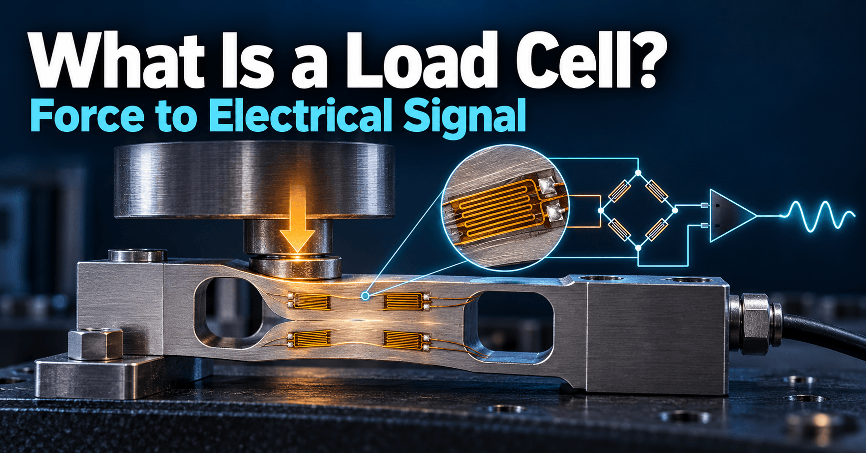
A load cell is a transducer that converts mechanical force into an electrical signal proportional to that force. Nearly every industrial load cell does this by bonding strain gauges to a precisely machined metal spring element (the "elastic element" or "flexure"). When force is applied, the flexure deforms by a few micrometers to a few hundred micrometers — far below its yield point — and the strain gauges convert that deformation into a resistance change. The relationship between applied force and flexure deformation is linear over the rated range, which is what makes the device useful as a measurement instrument rather than just a spring.
Role in measurement systems
In a measurement chain, the load cell is the first element: it sits between the physical world (a hopper full of grain, a truck axle, a robotic gripper) and the electronics that digitize and interpret the signal. Everything downstream — amplifier gain, ADC resolution, filtering, calibration constants — is chosen based on the load cell's electrical output characteristics. Get the load cell type or its electrical specification wrong and no amount of clever signal processing downstream fixes it; this is why datasheets assume you already understand the mechanical architecture before you start reading the electrical table.
Strain gauge fundamentals
A strain gauge is a thin conductive foil pattern on a polymer backing, bonded to the flexure so it stretches and compresses with it. Strain changes the foil's resistance via the geometric effect (length and cross-section change) and the piezoresistive effect of the conductor material. A typical metal-foil gauge has a gauge factor around 2, meaning a 1% change in length produces roughly a 2% change in resistance — but absolute resistance changes are tiny (fractions of an ohm on a 350 Ω gauge), which is why load cells use four gauges wired into a Wheatstone bridge rather than reading a single gauge directly. The bridge converts a minuscule resistance imbalance into a differential voltage that's practical to amplify.
Shear Beam Load Cells
Design and mechanical structure
A shear beam load cell is a machined metal beam, fixed at one end (or supported at both ends) with a web cut through its cross-section near the loading point. Strain gauges are mounted on this thinned web, oriented at 45° to the beam axis, where shear strain is maximum and bending strain is minimal.
Load application and stress distribution
Because the gauges respond to shear stress rather than bending moment, shear beam cells are far less sensitive to where along the beam the load is applied (load point variation) and to off-axis or eccentric loading. The shear strain in the web is nearly constant over a region of the beam, so small shifts in contact point don't significantly change the reading — a property bending beam designs lack.
Advantages and typical applications
This tolerance to load position makes shear beams the default choice for platform scales, truck scales, and tank/hopper weighing where the load can never be guaranteed to land on a single point. Capacities commonly range from a few hundred kilograms to over 50 tonnes. Shear beams are also relatively compact for their capacity compared to bending beams rated for the same load.
Output characteristics
Typical rated output for shear beam cells is 2 mV/V or 3 mV/V, with combined error (linearity, hysteresis, repeatability) often under 0.02% of rated output in precision-grade units. Datasheets will specify this per the relevant standard (OIML R60 or NIST Handbook 44 for legal-for-trade scales) — always confirm which standard a given cell was certified against before using it in a trade-certified system.
Bending Beam Load Cells
Cantilever and simply-supported configurations
A bending beam cell is either a cantilever (fixed at one end, loaded at the free end) or a simply-supported beam loaded at its center. Applying force bends the beam, putting one surface in tension and the opposite surface in compression.
Strain measurement on upper and lower surfaces
Gauges are mounted in matched pairs on the top and bottom surfaces of the beam, near the fixed end where bending moment — and therefore strain — is highest. The top-surface gauges see tension, the bottom-surface gauges see compression; wiring them into opposite arms of the bridge doubles the output sensitivity compared to a single active gauge and also provides first-order temperature compensation, since both gauges experience the same ambient temperature.
Sensitivity and linearity
Bending beam cells are generally more sensitive than shear beams at low capacities (under ~500 kg), making them attractive for bench scales and small platform scales. Their drawback is sensitivity to load point: moving the application point along the beam changes the bending moment at the gauge location, directly corrupting the reading. This makes bending beams unsuitable for applications where load position can't be tightly controlled.
Common use cases in platform scales and hoppers
Bending beams show up in retail and bench scales, small platform scales, and some hopper/silo weighing where load introduction is mechanically constrained (via a single pivot or linkage) so the load-point sensitivity is designed out of the system.
Column Load Cells
Compression-based design
A column (or compression) load cell is a solid or hollow cylindrical/barrel-shaped block of metal with strain gauges mounted axially and circumferentially on its outer surface. Under load, the column compresses axially and expands slightly radially (Poisson effect); the gauge bridge is wired to use both effects.
Axial loading requirements
Column cells require the load to be applied as close to pure axial compression as possible. Any bending moment introduced by a misaligned load path — a tilted platen, an off-center push rod — produces bending strain that adds error directly to the output, since the gauges can't distinguish "legitimate" axial strain from parasitic bending strain. Spherical washers or self-aligning load buttons are standard practice to enforce axial loading.
High-capacity applications
Because a column's cross-sectional area scales to resist force without a large increase in overall size, column load cells are the standard choice for high-capacity compression measurement — truck scale modules, silo and tank weighing, and press force monitoring from roughly 5 tonnes up to several hundred tonnes per cell. For pure high-capacity axial compression, this is the type to specify; shear or bending beams become mechanically impractical at those loads.
Stiffness and frequency response
Column cells are mechanically very stiff, which gives them high natural frequency and fast dynamic response — relevant in press and impact force applications where the force transient is on the order of milliseconds. Stiffness also means deflection at rated load is small (often under 0.1 mm), which matters when a system's mechanical design has tight clearance budgets.
Rated Output and Calibration
Definition of rated output (mV/V)
Rated output (RO) is the bridge's full-scale output voltage normalized to excitation voltage, expressed in mV/V. An RO of 2 mV/V with 10 V excitation yields 20 mV at full rated load. This normalization lets you compare cells regardless of what excitation voltage your instrumentation actually supplies.
Nominal versus maximum rated output
The datasheet's "rated output" is a nominal value with a manufacturing tolerance (e.g., 2 mV/V ± 0.1 mV/V); the actual calibrated value for a specific unit is printed on its calibration certificate and must be entered into your instrument, not the nominal datasheet figure. Confusing nominal and as-calibrated RO is a common source of multi-percent errors in field installations.
Temperature coefficient effects
Two temperature coefficients matter: temperature effect on zero balance (TC-Zero, typically %RO per °C) and temperature effect on span/sensitivity (TC-Span, %reading per °C). Over a 30°C ambient swing, an uncompensated cell with TC-Span of 0.002%/°C contributes 0.06% reading error — small, but it stacks with other error sources in a precision system and must be budgeted explicitly.
Calibration curves and linearity
Calibration is performed by applying known reference loads and recording output, producing a curve; deviation from the best-fit straight line is the nonlinearity spec, usually under 0.03% RO for precision cells. Combined with hysteresis and creep, these numbers define the practical accuracy floor of the whole measurement system no matter how good the downstream electronics are.
Selection Criteria for Load Cell Type
Load direction and magnitude
Pure axial compression at high capacity points to column cells; distributed or uncertain-contact-point loads in the tension-and-compression range point to shear beams; low-capacity, well-constrained loading points to bending beams. This single question — direction and magnitude of the dominant load — eliminates most of the candidate list before any electrical spec is considered.
Space and installation constraints
Column cells need a tall, narrow envelope and strict axial alignment hardware; shear beams need a longer footprint but tolerate less precise load introduction; bending beams need the least capacity-for-size headroom but the most control over where the load lands.
Environmental conditions
Washdown, outdoor, or hazardous-area installations push selection toward hermetically sealed stainless-steel cells rated IP68 or better, and in hazardous areas toward intrinsically safe signal conditioning — a consideration that also drives connectivity choices further downstream, which is where general industrial networking trade-offs like those discussed in Industrial IoT (IIoT) vs. Consumer IoT Differences become relevant once the sensor data has to leave the local panel.
Cost-performance trade-offs
Bending beams are typically the cheapest per unit at low capacity; shear beams cost more but tolerate installation imperfection, reducing commissioning cost; column cells cost the most per cell but are the only practical option at high capacity, so cost comparisons only make sense within a capacity class, not across types.
Integration into Measurement Systems
Signal conditioning and amplification requirements
A bridge output of a few millivolts needs a low-noise instrumentation amplifier with high common-mode rejection before any useful digitization can happen. The amplifier's input stage behavior — how it handles the bridge's differential signal riding on a common-mode voltage near half the excitation — is the same two-port and differential-amplification analysis covered generally in Two-Stage Op-Amp: Differential Input + Common-Source Output, and it's worth reviewing that material if you're designing the conditioning stage rather than buying an off-the-shelf module.
Wheatstone bridge configuration
The four strain gauges form a Wheatstone bridge: two arms increase in resistance under load, two decrease, so the bridge's null-balance output voltage scales with applied force while common-mode drift (from temperature, for instance) cancels to first order. Analyzing the bridge as a resistive network under excitation is a direct application of the voltage-divider reasoning in Voltage Divider and Current Divider Rules, and for more complex multi-cell summing-box configurations, the two-port parameter formalism in Two-Port Network Parameters: Z, Y, H, ABCD gives a cleaner way to model cable and connector loading effects than redriving the bridge equations from scratch each time.
Analog-to-digital conversion
A 2 mV/V cell at 5 V excitation with a 128x PGA gain and a 24-bit sigma-delta ADC is a common combination in weighing instruments, giving sub-microvolt effective resolution referred to the bridge input — enough headroom to resolve 1 part in 30,000 or better of rated capacity, though actual usable resolution is set by the load cell's own noise and nonlinearity, not the ADC.
System accuracy considerations
Worked example: a column cell rated 3 mV/V at 20,000 kg capacity, excited at 10 V, produces 30 mV full scale. If the system requires 1 kg resolution, that's 1 part in 20,000, or 1.5 µV per count referred to the bridge — achievable with a good 24-bit ADC and clean excitation, but only if cable resistance, EMI, and the cell's own 0.02% RO nonlinearity are all accounted for in the error budget rather than assumed away.
Learning
Sign in to track your progress.
Evidence
Public projects engineers linked to Load Cell: Types (Shear, Bending, Column), Rated Output.
No engineer has linked a project to this topic yet. Built something that proves it? Add the project and tag it with instrumentation-measurement-load-cell-types-shear-bending-column-rated-output — it then shows here and on your public profile.