
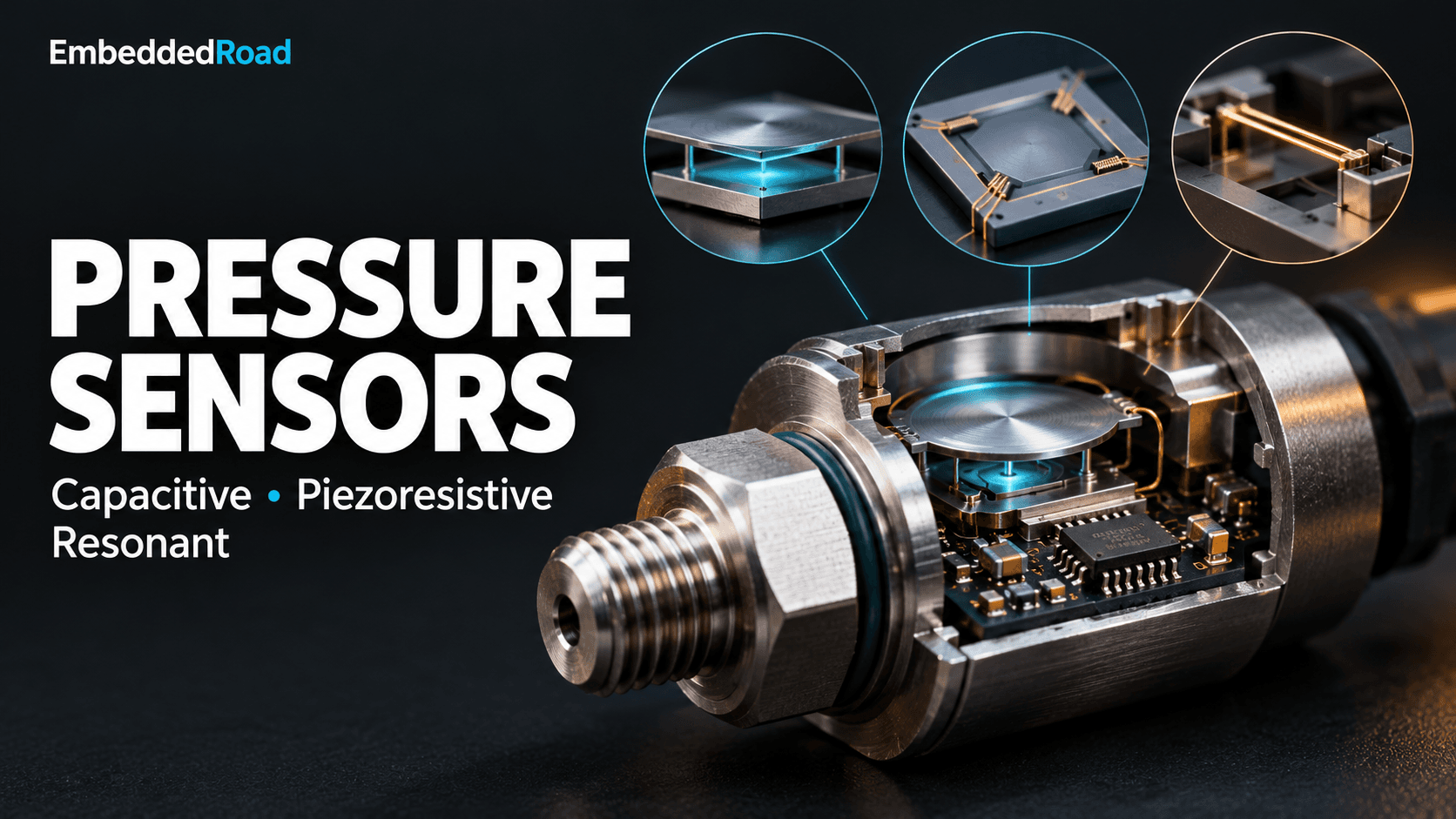
Pressure Sensor: Capacitive, Piezoresistive, Resonant
Compare capacitive, piezoresistive, and resonant pressure sensors - physics, signal conditioning, and trade-offs for embedded design.
Contents & prerequisites
Overview of Pressure Sensing Mechanisms
Pressure is one of the few physical quantities that embedded systems measure almost everywhere: tire inflation, HVAC duct static pressure, industrial hydraulics, medical ventilators, barometric altitude for drones, and process control loops in refineries. Unlike temperature or acceleration, pressure sensing requires a mechanical interface — a diaphragm, membrane, or beam — that converts a force per unit area into a measurable mechanical deflection or stress, which is then converted again into an electrical signal. That second conversion is where capacitive, piezoresistive, and resonant technologies diverge, and the choice has direct consequences for your analog front end, power budget, and firmware.
Why pressure sensing matters in embedded systems
A pressure reading is rarely the end goal — it's usually a proxy for something else: fluid level, flow rate (via differential pressure), altitude, leak detection, or mechanical load. Because the sensor sits at the physical boundary of the system, its transduction mechanism determines how much signal conditioning hardware you need, how sensitive the measurement is to temperature and vibration, and how much power the front end consumes while idling between samples. Picking the wrong technology doesn't just hurt accuracy — it can blow a power budget or require an ADC resolution you didn't plan for.
Three primary transduction methods compared
Piezoresistive sensors dominate general-purpose and automotive applications because they output a near-linear voltage from a simple resistive bridge. Capacitive sensors trade a more complex readout circuit for better long-term stability and lower power draw, making them common in consumer and medical devices. Resonant sensors sacrifice circuit simplicity and cost for metrology-grade accuracy, showing up in custody-transfer flow meters and aviation altimeters. All three can measure the same pressure range; the difference is in what you pay for in circuitry, power, and calibration effort.
Capacitive Pressure Sensors
Operating principle: deflection and capacitance change
A capacitive pressure sensor uses a thin conductive diaphragm suspended over a fixed electrode, separated by a small gap (typically a few micrometers to tens of micrometers). Applied pressure deflects the diaphragm toward the fixed plate, reducing the gap and increasing capacitance according to C = ε₀εᵣA/d. Because the relationship between deflection and pressure is mechanical (governed by diaphragm stiffness) and the capacitance-to-distance relationship is a simple inverse function, the overall transfer function is nonlinear, especially at larger deflections.
Diaphragm design and plate separation effects
Sensitivity depends on diaphragm thickness, radius, and the nominal gap: a thinner, larger diaphragm deflects more per unit pressure but is more fragile and more susceptible to burst overpressure. Designers typically keep peak deflection to a small fraction of the gap to stay in the quasi-linear region and avoid the diaphragm touching down on the fixed electrode (a hard failure mode called "snap-through" or "pull-in" in electrostatically actuated MEMS variants). Parasitic capacitance from bond pads, package leads, and PCB traces can be comparable to the sensing capacitance itself (often in the 1-10 pF range for MEMS devices), so layout and shielding matter as much as the sensor itself.
Advantages: low hysteresis, low power consumption
Capacitive sensing draws essentially no DC current — the plates don't conduct — so quiescent power is dominated by the readout ASIC, not the transducer. Diaphragms made from silicon or glass exhibit very low mechanical hysteresis, giving excellent repeatability across pressure cycles, which is why capacitive sensors are favored in battery-powered and duty-cycled IoT nodes.
Disadvantages: temperature sensitivity, signal conditioning requirements
Thermal expansion changes the gap and dielectric properties, and differential thermal expansion between the diaphragm and substrate introduces stress that mimics a pressure signal. Because the raw output is a small capacitance change (often sub-picofarad) riding on a larger baseline capacitance, you need a dedicated capacitance-to-digital converter or a carefully shielded charge-amplifier front end rather than a simple ADC input — parasitic cable capacitance alone can swamp the signal if the sensor isn't integrated with its readout IC.
Piezoresistive Pressure Sensors
Piezoresistive effect in doped silicon
Piezoresistive sensors implant resistors into a silicon diaphragm using boron or similar dopants. Mechanical stress from diaphragm deflection changes the resistors' resistivity through the piezoresistive effect — far more strongly than simple geometric strain would predict, since the effect is a property of the silicon crystal's band structure. Typical gauge factors for silicon piezoresistors run 50-100x higher than metal foil strain gauges, which is why silicon piezoresistive sensors can be made small while still producing usable signal levels.
Wheatstone bridge configuration and output scaling
Four piezoresistors are arranged in a Wheatstone bridge, two oriented to increase resistance under tensile stress and two to decrease under compressive stress, so the bridge output doubles relative to a single-arm measurement and common-mode (temperature-driven) resistance changes largely cancel. Output is typically specified in mV per volt of excitation per unit pressure (e.g., a sensor might be rated near 2-3 mV/V full scale — check the specific datasheet for the actual figure). Understanding how the bridge arms share excitation current and how loading affects the output node follows directly from the Voltage Divider and Current Divider Rules, since each bridge arm pair is effectively two voltage dividers whose midpoints are compared differentially.
Advantages: robust, direct electrical output, high sensitivity
The bridge output is a ratiometric voltage that scales directly with excitation, is straightforward to amplify, and the sensing element itself has no moving parts beyond the diaphragm flex, making it mechanically robust against shock and vibration.
Disadvantages: temperature drift, self-heating effects
Piezoresistor resistivity and gauge factor both vary with temperature, so an uncompensated bridge can drift several percent of full scale over a typical operating range — compensation networks or digital correction using an on-die temperature sensor are standard. Continuous bridge excitation also dissipates power in the resistors (self-heating), which both wastes energy in battery applications and introduces a slow thermal-zero drift that must be characterized separately from ambient temperature drift.
Resonant Pressure Sensors
Resonant frequency shift under pressure loading
A resonant pressure sensor couples the pressure-induced stress to a mechanical resonator — a vibrating beam, diaphragm, or quartz crystal — whose natural frequency shifts with axial stress, similar to how tightening a guitar string raises its pitch. Because frequency can be measured with extreme precision (parts per million) using a simple counter, the pressure resolution achievable this way exceeds what amplitude-based methods like piezoresistive bridges can deliver.
Vibrating beam and cantilever structures
Common implementations etch a beam or H-shaped resonator into silicon or quartz and drive it electrostatically or piezoelectrically at its resonant frequency, using a sustaining amplifier loop to maintain oscillation (the kind of feedback topology that shares design DNA with oscillator circuits built around Two-Stage Op-Amp: Differential Input + Common-Source Output architectures). Pressure applied to the diaphragm stresses the attached beam, shifting its resonant frequency in a highly repeatable, monotonic way.
Advantages: exceptional accuracy, excellent repeatability
Because frequency is inherently digital-friendly and immune to amplitude noise and cable resistance, resonant sensors achieve accuracy and long-term stability (often 0.01% of full scale or better, per typical manufacturer specs) well beyond piezoresistive or capacitive designs, which is why they're the default choice for custody-transfer and reference-grade barometric instruments.
Disadvantages: complexity, higher cost, frequency measurement requirement
The oscillator loop, vacuum or controlled-atmosphere packaging (needed to maintain a high mechanical Q), and the frequency-counting or lock-in readout electronics all add cost and design complexity compared to a bridge you can read with a simple instrumentation amplifier.
Signal Conditioning and Readout Electronics
Bridge conditioning for piezoresistive outputs
A piezoresistive bridge needs stable excitation (voltage or current), a precision instrumentation amplifier, and usually a lookup table or polynomial for temperature compensation using a co-located temperature sensor. A quick worked example: for a bridge excited at 5.0 V with a rated sensitivity of 2.5 mV/V at full-scale pressure, full-scale differential output is 5.0 V × 2.5 mV/V = 12.5 mV. With a gain-of-100 instrumentation amplifier, that becomes 1.25 V at the ADC — comfortably within a 12-bit converter's range, giving roughly 0.3 mV of pressure resolution per LSB before noise floor is considered.
Capacitive readout circuits and impedance measurement
Capacitive sensors require either a dedicated capacitance-to-digital converter (CDC) IC or a switched-capacitor charge amplifier referenced to an on-board reference capacitor; because the sensor is a two-terminal impedance rather than a voltage source, its behavior is best analyzed with Two-Port Network Parameters: Z, Y, H, ABCD when modeling parasitic coupling between the sense electrode and shield.
Frequency detection and lock-in techniques for resonant sensors
Resonant sensors need a sustaining oscillator plus a frequency counter (gated counter or reciprocal-counting timer peripheral) referenced to a stable clock; higher-end implementations use phase-locked loops or lock-in amplifiers to track frequency through noise and to reject off-resonance excitation energy.
Output linearization and temperature compensation
All three technologies are nonlinear to some degree over their full span and temperature range, so production firmware typically applies a polynomial correction (often second- or third-order in pressure and temperature) derived from factory calibration data stored in on-chip EEPROM or an external flash table.
Application Selection: Which Sensor Type?
Accuracy and stability requirements
If you need better than 0.1% long-term stability — custody transfer, reference barometers, aerospace altimetry — resonant is usually the only technology that gets there without frequent recalibration. Piezoresistive sensors are adequate for 0.5-1% applications like tire pressure monitoring or HVAC control.
Power budget and operating environment
Capacitive sensors win on quiescent power since there's no continuous excitation current through a resistive bridge; piezoresistive sensors can be duty-cycled (pulsed excitation) to save power but add settling-time constraints; resonant sensors require a continuously running oscillator loop, which usually rules them out for coin-cell, multi-year deployments.
Cost vs. performance trade-offs
Piezoresistive sensors are the cheapest per unit by a wide margin due to mature, high-volume MEMS fabrication. Capacitive sensors cost more due to the readout ASIC. Resonant sensors carry the highest cost because of the specialized packaging and precision frequency electronics, but that cost buys an order of magnitude or more improvement in stability.
Integration with IoT and embedded systems
For battery-powered IoT nodes, capacitive sensors paired with a low-power CDC are generally the best fit, since many commercial sensor-plus-ASIC combinations are designed for microamp-level sleep currents and burst-mode sampling. Industrial deployments have different priorities than consumer ones — the distinction is laid out well in Industrial IoT (IIoT) vs. Consumer IoT Differences — and industrial sites with wired power and a demand for traceable accuracy are where resonant and high-grade piezoresistive sensors earn their keep.
Real-World Considerations
Packaging and pressure port design
The sensor die must be isolated from the media it measures — gel-filled stainless steel ports are standard for piezoresistive sensors exposed to corrosive fluids, while capacitive and resonant sensors often require hermetic reference cavities to maintain a stable vacuum or sealed reference pressure for absolute measurements.
Reliability in harsh environments
Vibration and shock can excite a resonant sensor's structure at spurious frequencies, corrupting readings unless the mechanical design and lock-in detection reject off-resonance energy; piezoresistive sensors are comparatively forgiving of vibration since their output isn't frequency-dependent, but they're more exposed to media compatibility issues since the diaphragm often contacts the process fluid directly.
Calibration and field adjustment
All three sensor types ship with factory calibration coefficients, but field drift — from contamination, thermal cycling, or mechanical fatigue — eventually requires recalibration against a reference standard; resonant sensors drift the least over time, which is precisely why they're specified where recalibration intervals need to stretch to years rather than months.
Learning
Sign in to track your progress.
Evidence
Public projects engineers linked to Pressure Sensor: Capacitive, Piezoresistive, Resonant.
No engineer has linked a project to this topic yet. Built something that proves it? Add the project and tag it with instrumentation-measurement-pressure-sensor-capacitive-piezoresistive-resonant — it then shows here and on your public profile.