
Organ-on-Chip: Microfluidic Cell Culture and Biosensing
Organ-on-chip engineering explained: microfluidics, shear stress, TEER impedance sensing, and the BBB chip example for embedded and analog engineers.
Contents & prerequisites
What Is Organ-on-Chip Technology?
Definition and biological relevance
An organ-on-chip (OOC) is a microfluidic device, typically a few square centimeters, that contains living human cells arranged in channels and chambers engineered to reproduce the mechanical, chemical, and architectural context of a specific tissue. Unlike a well plate, which gives cells a static pool of medium, an OOC actively perfuses nutrients, imposes mechanical forces like flow-induced shear stress, and often stacks two or more cell types across a porous membrane to mimic a tissue interface — the gut epithelium next to capillary endothelium, for example, or neurons next to brain microvascular cells. The goal is not to grow more cells; it's to recreate the physiological boundary conditions those cells normally live in, so their gene expression, barrier function, and drug response look like the real organ rather than like a Petri dish.
Distinction from traditional cell culture and animal models
Static culture flattens cells onto plastic with no flow, no mechanical cues, and bulk nutrient concentrations that never reflect the steep gradients present in real tissue. Animal models supply systemic physiology but introduce species-specific metabolism, cost, ethical constraints, and timelines measured in months. OOC platforms sit between these two extremes: they use human cells (reducing translational mismatch) under engineered physical conditions (reducing the flat-culture artifact) at a timescale and cost closer to in vitro work. They are not a full replacement for either — a chip cannot model systemic immune response or whole-organism pharmacokinetics — but for localized tissue-tissue interactions, barrier function, and compound screening, they close a long-standing gap.
Why microfluidics matter in physiological mimicry
The defining engineering problem is scale. Real capillaries are 5–10 µm in diameter; nutrient and oxygen gradients in tissue occur over distances of 100–200 µm, the diffusion limit before cells become hypoxic. Microfluidic channels, typically 50–500 µm wide and tens of microns deep, are the only practical way to reproduce these length scales, flow rates, and gradient shapes on a benchtop device. This is why OOC design is as much a fluidics and electronics engineering discipline as a cell biology one.
Core Microfluidic Principles
Laminar flow and diffusion-based gradients
At the channel dimensions used in OOC devices, Reynolds numbers are almost always well below 1 (compare to ~2300 for turbulent transition in pipe flow), so flow is laminar and mixing between adjacent streams happens only by diffusion. This is a feature, not a limitation: engineers exploit it to create stable, predictable concentration gradients across a channel width — useful for dosing one side of a membrane without contaminating the other, or for studying chemotaxis. Because diffusion time scales with the square of distance, gradient stability depends heavily on channel width; doubling the width quadruples the time to equilibrate, which is a design lever worth using deliberately.
Shear stress effects on cell behavior
Vascular and epithelial cells are mechanosensitive. Endothelial cells exposed to physiological shear stress (on the order of 1–20 dyn/cm² depending on vessel type — check the specific tissue literature rather than assuming a universal number) align with flow, upregulate tight-junction proteins, and suppress inflammatory markers; the same cells under static or turbulent conditions behave more like diseased or activated tissue. Shear stress in a rectangular microchannel is set by flow rate, channel height, and viscosity, so the syringe pump or peristaltic pump driving the system is effectively a biological signal generator, not just a fluid-delivery mechanism.
Channel geometry and scale considerations
Channel cross-section determines both shear distribution and residence time. A tall, narrow channel produces a parabolic velocity profile with high wall shear but short residence time; a wide, shallow channel lowers shear but increases diffusion distance to cells not adjacent to the flow path. Every geometry choice is a trade-off between mechanical cue fidelity and mass-transport adequacy, and it has to be solved per cell type, since neurons and gut epithelium tolerate very different shear regimes.
Pressure-driven vs. electrokinetic transport
Most OOC platforms use pressure-driven flow — a syringe or peristaltic pump pushing medium through channels — because it is simple, cell-compatible, and produces predictable parabolic flow profiles. Electrokinetic transport (electroosmotic or electrophoretic flow, driven by an applied electric field across the channel) produces a flatter, plug-like velocity profile and allows flow control without moving parts, which is attractive for miniaturized, implantable, or highly integrated designs. The trade-off is that electrokinetic flow requires ionic buffers with controlled conductivity, generates some Joule heating, and can expose cells to electric fields and electrode byproducts (pH shifts, electrolysis bubbles) that pressure-driven systems avoid entirely. For most cell-viability-sensitive applications, pressure-driven flow remains the default; electrokinetic methods see more use in sample prep, particle sorting, and lab-on-chip analytics rather than sustained cell culture.
Cell Culture in Microfluidic Environments
Spatial organization and tissue structure
OOC chambers are usually two or more layers separated by a porous polymer membrane (commonly track-etched polycarbonate or PDMS, pore sizes in the 0.4–8 µm range), allowing one cell type to grow on each face while remaining physically and chemically coupled. This lets engineers reproduce the layered structure of real tissue — epithelium over stroma, endothelium under parenchyma — instead of a single monoculture monolayer.
Nutrient and waste exchange optimization
Flow rate must be tuned so that nutrient delivery and waste removal match cellular metabolic demand without imposing shear stress outside the physiological range. Too slow, and cells become nutrient-limited or waste-saturated, mimicking a diseased or necrotic state unintentionally; too fast, and non-vascular cell types (neurons, hepatocytes) experience mechanical stress they'd never see in vivo. This usually requires empirical tuning against known metabolic markers (lactate, glucose consumption) rather than a single formula.
Mechanical and chemical signaling cues
Beyond shear, some chips add cyclic mechanical strain (lung-on-chip stretching alveolar membranes to mimic breathing) or chemical gradients (oxygen tension gradients to mimic tissue depth). These require additional actuators — vacuum channels, gas-permeable membranes — layered into the same fabrication process as the fluidics.
Integration with extracellular matrix analogs
Cells rarely attach directly to bare polymer in a functional chip; a thin coating of collagen, fibronectin, or a synthetic ECM analog is deposited on channel surfaces first. This affects both biology (adhesion, differentiation) and fabrication (coating must survive sterilization and not clog narrow channels).
Biosensing Integration and Readout
Electrical impedance monitoring of cell viability
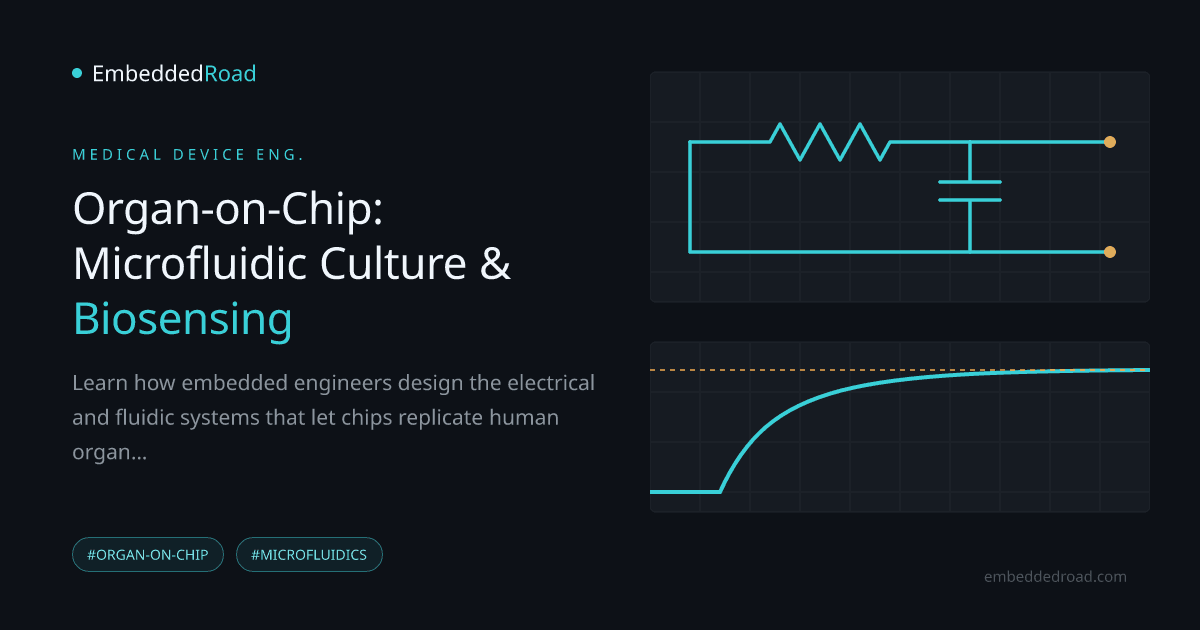
Embedding electrodes on either side of a cell layer lets you measure impedance across a frequency sweep, typically from a few Hz to the MHz range. A confluent, healthy monolayer presents higher impedance at low frequencies because cell membranes and tight junctions block current; as cells die or junctions open, impedance drops measurably in real time, without staining or destructive sampling. This is directly analogous to combining resistive and capacitive elements, and reading out the result in practice depends on the same resistor-network reasoning covered in Series and Parallel Resistor Combinations and the node-voltage bookkeeping in Kirchhoff's Voltage Law (KVL) and Mesh Analysis — the cell layer is just another impedance in the loop.
Optical biosensors embedded in chip architecture
Fluorescent reporters, embedded waveguides, or integrated photodiodes allow continuous optical readout (calcium flux, reporter-gene expression, oxygen-sensitive dyes) without removing the chip from its incubated environment. Optical and electrical readouts are often combined because they fail independently — bubbles disrupt impedance measurements but may not block an optical path, and vice versa.
Real-time metabolic and secretion tracking
Integrated electrochemical sensors (amperometric glucose/lactate electrodes, ELISA-on-chip for cytokines) allow continuous secretion tracking instead of discrete endpoint sampling, which matters because many physiological responses are transient and would be missed by single timepoint assays.
Signal conditioning and noise rejection
Biological impedance signals are small, drift with temperature, and ride on top of electrode polarization effects, so front-end amplification matters. A two-stage amplifier topology — high-gain differential input stage to reject common-mode noise from the shared bath electrolyte, followed by a common-source output stage for drive strength — is a standard building block for this kind of weak, noisy bioelectrical signal; see Two-Stage Op-Amp: Differential Input + Common-Source Output for the circuit-level reasoning. Because impedance changes are often reported logarithmically across a wide dynamic range, expressing shifts in decibels, as described in Decibel (dB): Voltage, Current, and Power Ratios, is common practice when comparing baseline versus compromised barrier states.
Physiology-on-Chip: Blood-Brain Barrier Example
Recreating barrier function with dual-chamber design
A blood-brain barrier (BBB) chip places brain microvascular endothelial cells in one channel and astrocytes or pericytes in an adjacent channel, separated by a porous membrane, with flow in the "vascular" channel providing physiological shear. This dual-chamber geometry is the direct microfluidic analog of the neurovascular unit.
Tight junction proteins and trans-endothelial electrical resistance (TEER)
Endothelial tight junctions (claudins, occludins) restrict paracellular transport, and their integrity is quantified electrically via TEER — essentially the same impedance measurement described above, read at low frequency and normalized to membrane area (Ω·cm²). A tight, functional BBB layer shows substantially higher TEER than a leaky one; tracking TEER over days gives a continuous, non-destructive readout of barrier maturation or breakdown, something a fixed-timepoint histology slide cannot provide.
Drug permeability testing without animal models
Once TEER confirms a stable barrier, compounds can be dosed in the vascular channel and sampled on the brain side to measure apparent permeability directly in human cells, avoiding species-specific transporter differences that often make rodent BBB data a poor predictor of human CNS drug exposure.
Relevance to neurovascular pathology
Because the barrier is instrumented and live, researchers can also model pathological states — hypoxia, inflammatory cytokine exposure, infection — and watch TEER and permeability shift in real time, which is useful for studying stroke, neuroinflammation, and barrier-disrupting diseases without invasive animal surgery.
Practical Engineering Challenges
Fabrication methods and material biocompatibility
PDMS (soft lithography) remains the most common prototyping material because it's optically clear, gas-permeable, and easy to mold, but it absorbs small hydrophobic drug molecules, which can silently invalidate a permeability assay. Thermoplastics (COC, PMMA) and glass are used for production-grade or drug-screening chips specifically to avoid this absorption problem, at the cost of more complex fabrication (hot embossing, injection molding, bonding).
Bubble nucleation and channel clogging prevention
Dissolved gas coming out of solution at temperature or pressure changes forms bubbles that lodge in narrow channels and locally block flow — a failure mode that can silently starve a region of cells for hours before it's noticed. Degassing media, priming channels under vacuum, and avoiding sharp cross-section transitions are standard mitigations; channel design should avoid dead-end pockets where bubbles nucleate and never clear.
Protein adsorption and non-specific binding
Serum proteins and secreted factors adsorb onto channel walls, especially PDMS, skewing both biology (signaling molecules depleted from solution) and sensor readings (biosensor surfaces fouled). Surface treatments (plasma oxidation, PEGylation) help but degrade over culture duration, so long-term chips need a re-conditioning or surface-stability plan, not a one-time treatment.
Long-term culture stability and sterilization
Multi-week cultures require sterile, leak-free fluidic connections maintained over time, and sterilization methods (autoclave, ethylene oxide, gamma, UV) all have different compatibility profiles with chip materials and bonded interfaces — a treatment that's fine for glass may delaminate a PDMS-thermoplastic bond.
Clinical and Regulatory Pathways
Validation against traditional in vitro and in vivo benchmarks
Before an OOC result is trusted, it has to be benchmarked: does the chip's drug response correlate with known clinical outcomes or established animal data for reference compounds? This validation step, compound by compound and tissue by tissue, is slow and is the current bottleneck for broader adoption.
Reproducibility, standardization, and scaling
Chip-to-chip and lab-to-lab variability — in flow rate control, cell sourcing, membrane pore density — remains a real limitation. Standardized fabrication tolerances and shared reference protocols are an active area of industry and consortium effort rather than a solved problem.
FDA perspective on organ-chip models for drug testing
Regulatory agencies, including the FDA, have expressed openness to organ-chip and other New Approach Methodologies as supplementary or, in specific contexts, alternative evidence to animal testing, particularly following legislative changes that no longer mandate animal studies for all drug approvals. Check current FDA guidance documents directly, since this is an evolving policy area rather than a fixed rule.
Future role in personalized medicine and disease modeling
Chips seeded with a specific patient's induced pluripotent stem cells offer a path toward patient-specific drug response prediction — still largely a research-stage application, but one that depends entirely on the fabrication, biosensing, and electronics reliability described above scaling down to routine, low-cost manufacture.
Learning
Sign in to track your progress.
Evidence
Public projects engineers linked to Organ-on-Chip: Microfluidic Cell Culture and Biosensing.
No engineer has linked a project to this topic yet. Built something that proves it? Add the project and tag it with medical-devices-organ-on-chip-microfluidic-cell-culture-and-biosen — it then shows here and on your public profile.