
Humidity Sensor: Capacitive, Resistive, Psychrometric
Compare capacitive, resistive, and psychrometric humidity sensors by physics, signal conditioning, accuracy, and deployment trade-offs.
Contents & prerequisites
Why Humidity Measurement Matters in Embedded Systems
Moisture content in air drives corrosion rates, condensation risk, material degradation, and human comfort. An embedded system that controls or logs environmental conditions is almost always acting on a humidity reading somewhere in its control loop, whether that loop closes in milliseconds (industrial process control) or over months (archival storage monitoring).
Applications: HVAC, environmental monitoring, and industrial control
HVAC systems use relative humidity (RH) to modulate dehumidification and ventilation, targeting comfort bands typically between 30% and 60% RH. Environmental monitoring stations track RH alongside temperature and pressure for weather and agricultural applications, often at remote, unpowered, or solar-powered sites. Industrial control applications — pharmaceutical cleanrooms, semiconductor fabs, grain silos, and paper mills — use humidity as a process variable that directly affects product yield or safety margins. Each of these contexts imposes different constraints on sensor choice: HVAC favors low-cost capacitive modules, industrial process control may demand psychrometric-grade accuracy, and field monitoring must tolerate condensation and contamination without destroying the sensor.
Measurement challenges in real-world deployments
Real deployments rarely match datasheet test conditions. Condensing environments can saturate a capacitive sensor's polymer film; dust and industrial solvents degrade both capacitive and resistive elements; temperature gradients between the sensor and the measured air introduce systematic errors because RH is temperature-dependent. A sensor reading 45% RH at the probe tip may not represent the air three centimeters away if there's a thermal gradient from nearby electronics. Self-heating from onboard signal conditioning circuitry is a frequent, underappreciated error source — a sensor dissipating 5 mW in a poorly ventilated enclosure can bias local temperature by a degree or more, which shifts the RH reading materially.
Trade-offs between sensor types and cost
Capacitive sensors dominate mass-market and industrial applications because they are cheap, small, and directly digitizable. Resistive sensors trade some accuracy and long-term stability for simplicity and low cost, particularly in high-volume consumer products. Psychrometric methods deliver the best absolute accuracy and serve as the calibration reference against which both electronic sensor types are validated, but they require moving parts (wet-bulb wicking and airflow) and routine maintenance, making them unsuitable for most embedded deployments. Choosing among them is a question of required accuracy, acceptable maintenance burden, and unit cost at the volumes you're building.
Capacitive Humidity Sensors: Operating Principle
Dielectric constant change with moisture absorption
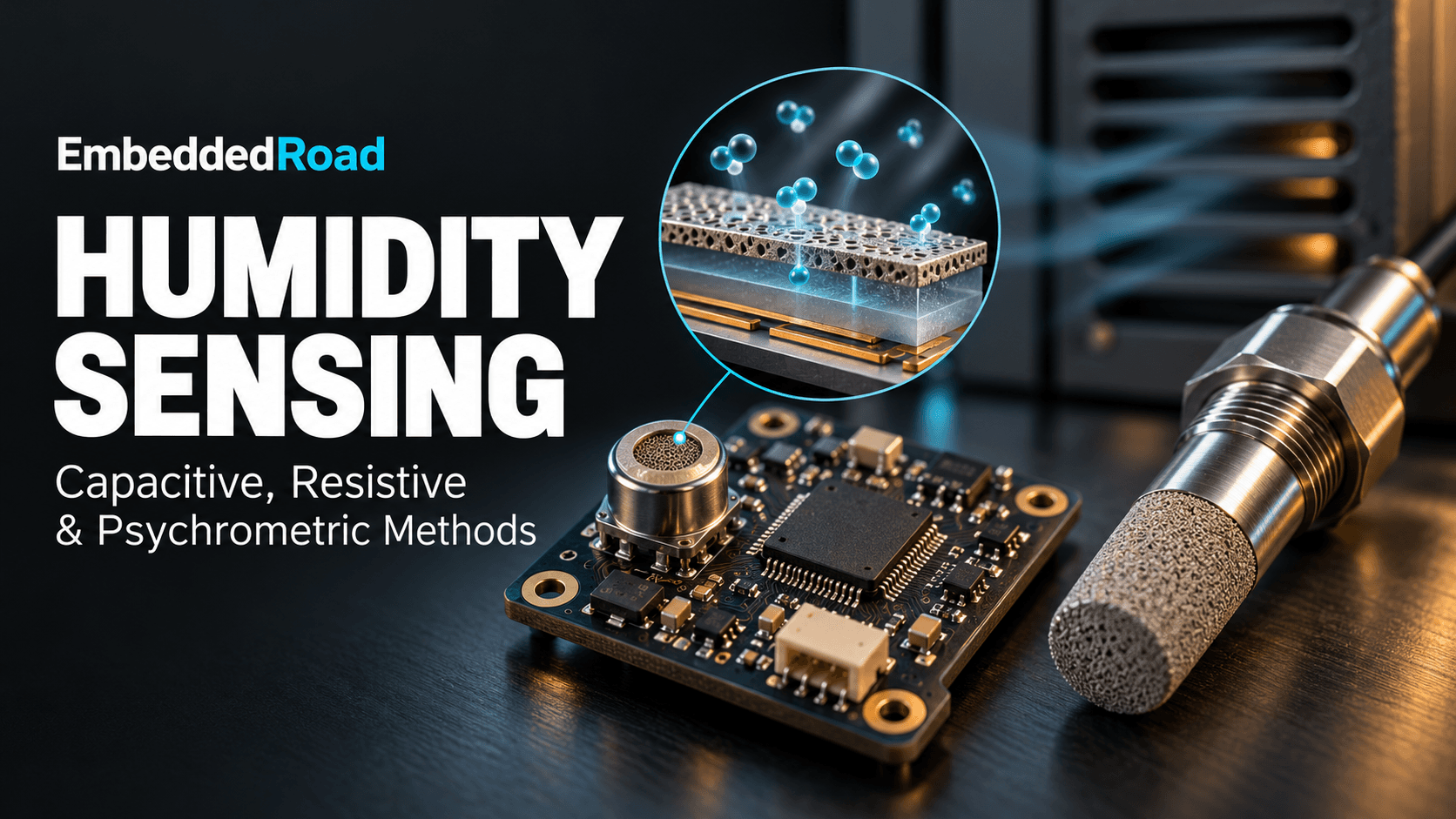
A capacitive humidity sensor consists of a thin hygroscopic polymer or metal-oxide film sandwiched between two electrodes, one of which is porous to let water vapor reach the dielectric. Water molecules have a relative permittivity (~80) vastly higher than the dry polymer (typically 2–5), so as the film absorbs moisture proportional to ambient RH, the sensor's capacitance increases roughly linearly with RH over much of its range — commonly a few hundred picofarads changing by 0.2–0.5 pF per %RH, though exact slope and baseline must be taken from the specific device's datasheet.
Capacitance-to-frequency conversion in signal conditioning
Because the capacitance change is small relative to parasitic capacitance in cabling and PCB traces, most capacitive humidity sensors are conditioned with an on-board oscillator that uses the sensor as the timing element, converting capacitance to frequency. A simple relaxation oscillator (555-type or dedicated ASIC) charges the sensor capacitance through a fixed resistance and compares against a threshold, producing a square wave whose period shifts with RH. This moves the sensitive analog node onto the sensor package itself, minimizing the length of high-impedance wiring exposed to noise.
Frequency output and digital integration
A frequency output is trivial for an MCU to digitize: route it to a GPIO configured as a timer capture input or counter gate, and measure period or frequency directly without an ADC. This is a major integration advantage — no precision reference voltage, no analog front end, just a timer peripheral and a lookup table or polynomial to convert frequency to %RH. Many modern capacitive sensors skip the discrete frequency stage entirely and integrate an ASIC that outputs I2C or SPI digital RH and temperature readings directly, which is now the default choice for new embedded designs.
Typical accuracy and hysteresis characteristics
Capacitive sensors typically specify accuracy in the ±2% to ±5% RH range across 0–100% RH, with hysteresis (difference in reading between rising and falling humidity at the same actual RH) of 1–3% RH being common for polymer-film devices. This hysteresis arises from the physical absorption/desorption lag in the film and is usually characterized and partially compensated in the sensor's factory calibration curve — check the datasheet's hysteresis plot, not just the headline accuracy number, before specifying a sensor for an application with cyclic humidity swings.
Resistive Humidity Sensors: Impedance-Based Detection
Resistance variation across hygroscopic polymer films
Resistive (impedance) humidity sensors use a hygroscopic salt or conductive polymer film whose ionic conductivity changes with absorbed moisture. As RH rises, more water molecules dissociate ionic salts embedded in the film, lowering its bulk resistance — often by two to three orders of magnitude across the full 0–100% RH range. This large dynamic range is an advantage for simple threshold detection but complicates building a single linear analog front end that covers the full span with consistent resolution.
Impedance measurement using voltage divider circuits
The standard conditioning approach places the sensor as one leg of a voltage divider, with an AC excitation signal (typically 100 Hz–1 kHz) rather than DC. AC excitation is mandatory, not optional: a DC bias across the ionic film causes electrolytic polarization, which permanently degrades the sensing element within hours. The divider's output is then rectified and buffered before reaching the ADC, and the divider's fixed resistor value must be chosen to center the AC output swing within the sensor's useful resistance range given the expected RH span of the application.
Signal conditioning and temperature compensation
Because ionic conductivity is also a strong function of temperature, resistive humidity sensors require a co-located temperature measurement and a compensation polynomial (often supplied in the datasheet as a correction table or NTC-paired circuit) to convert raw impedance to actual RH. This compensation is typically computed in firmware after an ADC read, which means the MCU must also manage synchronized temperature sampling. A two-stage op-amp buffer stage is common here to present a high input impedance to the divider's AC-coupled output without loading it down and skewing the resistance reading.
Response time and drift over sensor lifetime
Resistive sensors generally respond more slowly to step changes in RH (time constants of tens of seconds to a few minutes) than capacitive sensors, and they are more prone to long-term drift from contamination — airborne solvents, dust, and salts can alter the film's baseline resistance by several percent RH-equivalent over a year of continuous industrial exposure. For applications requiring stable readings over multi-year deployment without recalibration access, this drift characteristic should be weighed heavily against the lower unit cost.
Psychrometric Method: Wet and Dry Bulb Principle
Thermodynamic basis of relative humidity calculation
A psychrometer measures RH indirectly through evaporative cooling. Two thermometers are used: a dry-bulb thermometer reading ambient air temperature, and a wet-bulb thermometer whose sensing tip is wrapped in a water-saturated wick. Air flowing across the wet bulb evaporates water, and the cooling rate depends on how far the surrounding air is from saturation — dry air evaporates water faster, producing a larger wet-bulb depression (the temperature difference between dry and wet bulb). This depression, combined with ambient pressure, is a direct thermodynamic measurement of vapor pressure deficit, from which RH is calculated without relying on any empirically-drifting sensing film.
Dual temperature measurement setup
A practical psychrometric instrument needs two matched temperature sensors (RTDs or precision thermistors are typical for instrumentation-grade builds), forced airflow across the wet bulb at a controlled velocity (commonly around 3–5 m/s in sling or aspirated psychrometer designs — confirm against the specific instrument's manual), and a continuously wetted wick. The airflow requirement is what prevents most psychrometers from being passive, maintenance-free embedded components; they need either a fan or manual slinging, plus periodic wick rewetting and replacement.
Psychrometric chart interpretation
RH is derived from dry-bulb and wet-bulb temperatures using psychrometric charts or the underlying Carrier equation, which relates vapor pressure to the wet-bulb depression and barometric pressure. Embedded implementations typically replace chart lookup with a firmware calculation using published polynomial approximations of the psychrometric relationship, taking dry-bulb temperature, wet-bulb temperature, and local barometric pressure as inputs and returning RH directly — pressure compensation matters here since the relationship shifts with altitude and weather-driven pressure changes.
Advantages in high-accuracy laboratory applications
Because the psychrometric method measures a thermodynamic quantity rather than a material property of a sensing film, it does not suffer the long-term drift or contamination sensitivity of polymer-based sensors, and it is the method typically used to generate reference-grade calibration standards for capacitive and resistive sensors. The trade-off is maintenance: wicks dry out, airflow sources fail, and the method is impractical for unattended field deployments or anywhere water supply and airflow can't be guaranteed.
Signal Conditioning and Output Interfaces
Analog voltage, current loop, and digital outputs
Industrial humidity transmitters commonly offer three output formats: 0–5 V or 0–10 V analog voltage, 4–20 mA current loop, or digital buses (I2C, SPI, Modbus RTU over RS-485). Current loop outputs are preferred for long cable runs in industrial settings because the signal is immune to voltage drop and noise pickup over distances exceeding tens of meters, and the live-zero (4 mA minimum) allows open-circuit fault detection. Digital outputs are preferred for short-haul embedded integration where the MCU can host the bus directly and skip analog front-end design entirely.
Op-amp configurations for impedance conversion
Both capacitive and resistive sensor front ends frequently need op-amp stages to convert high-impedance sensor signals into low-impedance signals suitable for ADC sampling or long-distance transmission. A transimpedance or buffer configuration prevents the ADC's sample-and-hold capacitor from loading the sensor circuit and distorting the reading, and a differential-input stage helps reject common-mode noise picked up along cable runs in electrically noisy industrial environments.
Filtering and linearization techniques
Raw sensor output — whether frequency, voltage, or resistance — is rarely linear in RH across the full range. Firmware typically applies a polynomial correction (often a 2nd or 3rd order fit against the factory calibration curve from the datasheet) along with a low-pass digital filter to reject the inherent noise of ionic/dielectric sensing elements. A moving average or IIR filter with a time constant matched to the sensor's physical response time avoids over-filtering (adding unnecessary lag) or under-filtering (passing sensor noise through to the control loop).
IoT integration and wireless transmission
For distributed monitoring, humidity sensors increasingly report over wireless links (LoRaWAN, Zigbee, cellular) rather than wired current loops, particularly in agricultural and facility-wide environmental monitoring. This shifts the design concern from cabling and noise immunity to battery life and report interval; a capacitive sensor's digital I2C interface pairs well with a low-power MCU that wakes, samples, transmits, and sleeps, since there's no need to keep an analog front end powered continuously. These considerations differ meaningfully between consumer and industrial deployments — see the distinctions covered in Industrial IoT (IIoT) vs. Consumer IoT Differences — and humidity data is also a common input to building-level Energy Management IoT systems, where RH feeds dehumidification and HVAC load calculations alongside power sub-metering data.
Selecting a Humidity Sensor for Your Application
Performance comparison: range, accuracy, and temperature stability
Capacitive sensors generally offer the best balance of range (0–100% RH, including condensing conditions for ruggedized variants), moderate accuracy (±2–5% RH), and compact digital integration. Resistive sensors offer lower cost at the expense of slower response and higher long-term drift, and are best suited to threshold-type applications (e.g., "alert above 70% RH") rather than precision control loops. Psychrometric instruments offer the best absolute accuracy but require maintenance infrastructure incompatible with most embedded form factors.
Cost and integration complexity
Unit cost scales roughly in the order resistive < capacitive (discrete) < capacitive (digital ASIC) < psychrometric instrument, but integration engineering cost scales in the opposite direction in some respects — a digital capacitive sensor module is often cheaper in total engineering hours than a resistive sensor requiring custom AC excitation and temperature compensation firmware, even if the resistive part itself costs less.
Environmental constraints: corrosion, drift, calibration
Condensing environments, airborne contaminants, and chemical exposure (ammonia, solvents, salt fog) all degrade sensing films over time. Industrial sensor datasheets specify a long-term drift figure, typically expressed as %RH per year, which should directly inform your recalibration interval. Sensors deployed in cleanroom or sealed enclosures will drift far less than those in open industrial airflow.
Datasheets and specification sheets: what to check
When comparing candidate sensors, verify: full accuracy curve across the operating RH range (not just a single best-case number), hysteresis width, response time (t63 or t90), long-term drift rate, operating temperature range and whether accuracy derates outside a narrow band, and whether the stated accuracy already includes or excludes temperature compensation.
Practical Implementation Considerations
Mounting and ventilation requirements
Humidity sensors must be mounted where airflow reaches the sensing film without exposing it to direct condensation, splashing, or dust accumulation. A vented enclosure with a hydrophobic membrane (Gore-Tex-style filter) is standard practice for sensors mounted in outdoor or washdown environments — it passes water vapor while blocking liquid water and particulates.
Calibration intervals and recalibration methods
Standard practice is recalibration against a salt-solution reference (saturated salt solutions produce known fixed RH values, e.g., sodium chloride near 75% RH at room temperature — confirm exact figures from a calibration reference standard) at intervals set by the sensor's datasheet drift specification, commonly annually for industrial capacitive sensors.
Common failure modes and preventive maintenance
Typical failure modes include film saturation after condensation exposure (recoverable after a bake-out cycle for some capacitive sensors, per manufacturer instructions), chemical poisoning from solvent exposure (usually permanent), and connector corrosion in humid outdoor installations. Preventive maintenance should include periodic visual inspection of the vent filter for blockage and a scheduled comparison reading against a reference instrument to catch drift before it affects downstream control decisions.
Learning
Sign in to track your progress.
Evidence
Public projects engineers linked to Humidity Sensor: Capacitive, Resistive, Psychrometric.
No engineer has linked a project to this topic yet. Built something that proves it? Add the project and tag it with instrumentation-measurement-humidity-sensor-capacitive-resistive-psychrometric — it then shows here and on your public profile.