
Electrical Protective Means: Double Insulation, Reinforced Insulation
Learn how double insulation and reinforced insulation satisfy IEC 60601-1 shock protection, with test criteria, creepage rules, and design trade-offs.
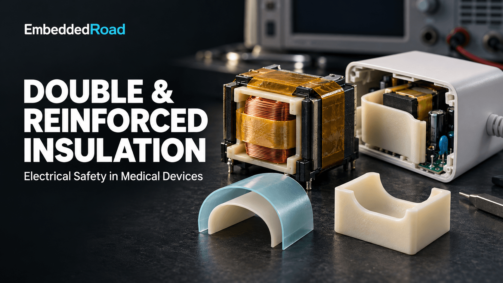
Contents & prerequisites
Why insulation alone isn't enough: Risk-based protection strategy
A single layer of insulation between a patient-connected conductor and a hazardous voltage is never acceptable in medical device design, because a single fault — a crack, a puncture, a contaminated gap — removes it entirely and leaves nothing standing between the patient and mains potential. IEC 60601-1 solves this with a "two-fault" philosophy: between any hazardous voltage and any accessible or patient-connected part, there must be protection means that survive two independent faults before a shock hazard reaches the patient or operator. Double insulation and reinforced insulation are the two accepted ways to satisfy that requirement without relying on protective earth as the sole safeguard.
Single insulation failure modes in patient-connected equipment
Basic insulation alone fails through mechanisms that are individually plausible and collectively inevitable over a device's service life: dielectric puncture from a transient overvoltage, mechanical abrasion against a moving part, thermal degradation that embrittles a polymer, and tracking — the formation of a carbonized conductive path across a contaminated or moistened surface. In a single-fault-tolerant design, any one of these turns a benign enclosure into a live one. For a device that touches skin, mucosa, or an invasive catheter, that failure mode is not a product return — it's a reportable adverse event.
How risk management drives insulation architecture decisions
The insulation architecture is an output of the risk management file required by ISO 14971, not an input chosen first. A patient-applied part on a circuit carrying mains-derived voltage drives a different means-of-protection (MOP) allocation than an internally powered, battery-only sensor housing. The design team decides early whether the protection against electric shock lives in the power supply (2 MOPP, two means of patient protection), is split between the supply and the applied part (1 MOOP + 1 MOPP), or is entirely MOOP (means of operator protection) for a device with no patient contact. That allocation, documented against each conductor pair in the schematic, is what tells the mechanical and materials engineers whether they need double insulation, reinforced insulation, or both.
Regulatory expectations under IEC 60601-1 for electrical safety
IEC 60601-1 Clause 8 specifies the insulation diagram, the dielectric strength test voltages, and the creepage/clearance tables (largely drawn from IEC 60664-1) that a notified body will check line by line. The standard does not care which construction you choose as long as the end state — two independent, testable protective barriers — is demonstrable. Reviewers expect an insulation diagram showing every MOOP/MOPP boundary, cross-referenced to the bill of materials and to the dielectric test report.
Double insulation: Dual independent barriers to reduce shock hazard
Double insulation is basic insulation plus a second, independent supplementary insulation layer, each capable of withstanding the full working voltage on its own. The two layers together satisfy the two-fault requirement because one layer must fail and then the other must independently fail before a shock path exists.
Definition and construction of basic + supplementary insulation layers
Basic insulation is the layer that makes the product function safely under normal conditions — the enamel on a transformer winding, the extruded jacket on a mains lead. Supplementary insulation is added specifically as the second independent barrier: a separate molded housing shell, an additional sleeve, or a second winding layer with its own dielectric path. The two layers must be physically and electrically separable in the failure sense — a shared failure mechanism (same material batch defect, same mechanical stress point) defeats the purpose.
How two independent faults are required to create hazard
If basic insulation cracks due to vibration and supplementary insulation is a mechanically unrelated structure — a different material, a different mounting, a different stress path — the probability that both fail from the same event is treated as negligible under IEC 60601-1's single-fault-safe model. This is why the standard requires independence to be demonstrable, not assumed from the fact that two layers exist in a stack-up.
Material and spacing requirements for independence
Independence is tested through construction, not declared in a datasheet. Two layers of enamel on the same wire do not count as double insulation because a single scrape removes both simultaneously. IEC 60601-1 requires creepage and clearance distances for each layer individually, sized per the working voltage and pollution degree tables in IEC 60664-1, and reinforced or basic insulation thickness minimums (commonly referenced as ≥0.4 mm per layer for thin-sheet barriers, verified against the specific edition in use) unless the layer passes an impulse/dielectric test that justifies a thinner construction.
When double insulation eliminates need for grounding
Double insulation can eliminate the need for protective earth only at the equipment-class level, and only when every other accessible conductive part is likewise protected by an equivalent MOOP/MOPP — this is the basis of Class II medical equipment construction. A device built this way has no protective earth pin, because the two-fault shock path through the enclosure has already been engineered out. Internally, however, a Class II device can still require protective earth on specific internal subassemblies (e.g., a metal chassis supporting a mains transformer) if those are not themselves double- or reinforced-insulated from the hazardous circuit — eliminating grounding is a system-level property, not a blanket exemption.
Reinforced insulation: Single layer with higher dielectric strength
Reinforced insulation is a single insulation structure that provides the same degree of protection as double insulation, achieved through higher dielectric strength, greater thickness, and tighter tracking-resistance control rather than through a second physical layer.
How thicker or higher-grade insulation replaces dual layers
A reinforced layer must meet the combined creepage, clearance, and dielectric withstand requirements that double insulation would achieve across both its layers. In practice this means specifying a polymer with a higher Comparative Tracking Index (CTI), increasing the physical path length for creepage, or using a potting/conformal-coating process that closes off the contamination paths that would otherwise require a second mechanical barrier.
Dielectric voltage withstand and tracking resistance criteria
Reinforced insulation at a given working voltage must pass a dielectric withstand test at the test voltage specified for 2 MOPP/2 MOOP in IEC 60601-1 Table 13 (look up the exact figure for your working voltage and insulation type in the current edition), and it must meet a minimum CTI — commonly Pollution Degree 2 material groups require CTI ≥175 or ≥400 depending on the clearance reduction claimed under IEC 60664-1. Tracking resistance matters because reinforced insulation has no redundant layer to fall back on if a contamination path forms.
Comparison of reinforced vs. double insulation in space-constrained designs
| Factor | Double insulation | Reinforced insulation |
|---|---|---|
| Physical layers | Two independent barriers | One barrier, higher spec |
| Typical thickness/space | Larger stack-up | Thinner, saves board/enclosure space |
| Failure independence | Must be demonstrated by construction | Not applicable (single barrier) |
| Manufacturing complexity | Two processes, two inspections | One process, tighter process control |
| Best fit | Enclosures, cabling, mechanical barriers | PCB isolation gaps, connectors, compact housings |
Cost and manufacturing trade-offs
Double insulation often costs less per unit in high-volume plastic enclosures because two standard-grade materials molded separately are cheaper than one exotic high-CTI compound. Reinforced insulation wins in space-constrained PCB layouts and connectors, where adding a second physical layer isn't geometrically possible, but it demands tighter incoming-material QC because there's no second barrier to catch a single bad batch.
Electrical safety testing and validation for medical devices
Validation of either construction rests on dielectric withstand, tracking/erosion, and dimensional verification, documented to a level a notified body auditor can trace without asking follow-up questions.
Dielectric strength testing protocols and pass/fail criteria
The dielectric (hi-pot) test applies an AC or DC test voltage derived from the working voltage and MOPP/MOOP classification per IEC 60601-1 Table 13, held for 60 s (or 1 s for production-line screening per the manufacturer's validated correlation), with pass defined as no breakdown or disruptive discharge. Test voltages for 2 MOPP are substantially higher than for 1 MOPP at the same working voltage — confirm the exact multiplier in the current edition rather than assuming a round number.
Tracking and erosion assessment under humid/contaminated conditions
Comparative Tracking Index testing per IEC 60112 and humidity preconditioning per IEC 60601-1 Clause 5.7 simulate the contaminated, moist conditions a device may see in a hospital cleaning cycle. A reinforced barrier that passes dry dielectric testing but hasn't been through humidity preconditioning has not been validated for real deployment conditions.
Partial discharge and insulation thickness verification
For higher-voltage circuits, partial discharge testing detects incipient voids in the insulation that a straight hi-pot test can miss, and physical cross-sectioning or non-destructive thickness gauging confirms the minimum distance-through-insulation figure used in the risk file. Electromagnetic immunity testing under IEC 60601-1-2 basic/enhanced performance criteria is a separate program but shares the same insulation diagram — an ESD event that punctures a barrier is an electrical safety failure, not just an immunity failure.
Documentation for notified body and regulatory submission
Submission packages need the insulation diagram, the dielectric and CTI test reports with instrument calibration records, the materials data sheets showing CTI and thickness, and a traceability matrix linking each insulation claim to a specific test report and risk control measure in the ISO 14971 file.
How accelerated aging affects long-term insulation integrity
Insulation that passes initial dielectric testing can still fail in the field if the polymer degrades faster than the device's claimed shelf life, so aging data has to be generated, not assumed.
Thermal, electrical, and moisture stress on polymer insulation
Thermal cycling embrittles plasticizers and accelerates oxidation, sustained electrical stress accelerates partial-discharge-induced treeing in voids, and moisture ingress lowers surface resistivity and promotes tracking — all three stresses act simultaneously in real devices, not in isolation.
Predicting end-of-life performance during device shelf life
Accelerated aging protocols following the methodology in ASTM F1980 real-time equivalent calculation let engineers condition insulation samples at elevated temperature for a calculated duration and then re-run the dielectric and CTI tests to confirm the barrier still meets spec at the end of claimed shelf life, not just at time zero.
Material selection to maintain safety barriers over product lifetime
Choosing a polymer with margin above the minimum CTI and dielectric requirement — rather than one that barely passes at time zero — gives headroom against the degradation curve and avoids a shelf-life claim that collapses under aging data late in development.
Design decisions: When to choose double vs. reinforced insulation
Patient contact risk and voltage class of the circuit
A circuit directly connected to a patient-applied part carrying mains-derived voltage needs the full 2 MOPP allocation, and the choice between double and reinforced insulation there is driven by geometry as much as voltage class — both satisfy the same risk requirement.
Enclosure geometry and accessibility constraints
Large enclosures and cabling favor double insulation because adding a second molded shell or sleeve is cheap and doesn't compete for space. Compact connectors, PCB isolation slots, and transformer windings favor reinforced insulation because there's no room for a second physical structure.
Manufacturing capability and cost impact
A contract manufacturer already tooled for two-shot molding can produce double-insulated enclosures at low marginal cost; a manufacturer without that capability may find a single reinforced-grade resin cheaper to qualify even at a higher per-kilogram material cost.
Creepage and clearance distance interplay
Creepage and clearance distances scale with working voltage, pollution degree, and material group per IEC 60664-1, and reinforced insulation generally requires larger creepage/clearance figures than a single layer of basic insulation at the same voltage — look up the exact millimeter values for your working voltage, pollution degree, and MOPP/MOOP count in the current IEC 60601-1 and IEC 60664-1 tables, since they are not interchangeable across editions.
Common failure modes and how design prevents them
Insulation puncture from internal component stress or creepage
Sharp internal edges, stressed solder joints, and vibration-induced wire chafe puncture insulation locally; design margin comes from routing high-voltage conductors away from mechanical stress points and specifying minimum bend radii on insulated cable in the assembly drawing.
Moisture ingress and tracking paths in damp environments
Condensation inside a sealed enclosure after a cold-to-warm transport cycle is a common field failure precursor; conformal coating and drainage/venting design reduce the dwell time of moisture on creepage surfaces.
Contamination and conductive paths between conductors
Dust and conductive residue bridging a creepage path is addressed by minimum pollution-degree-appropriate spacing and, where cleaning agents are expected, by selecting housing materials resistant to the specific disinfectants in the device's cleaning instructions.
Design margins and redundancy in critical patient-contact circuits
Building in creepage and dielectric margin beyond the table minimum — rather than designing exactly to the limit — absorbs manufacturing variance and aging degradation without requiring a redesign when a later test report shows a marginal pass.
Related reading
- Electrical Safety: Protective Earth, Leakage — protective earth and leakage testing.
Learning
Sign in to track your progress.
Evidence
Public projects engineers linked to Electrical Protective Means: Double Insulation, Reinforced Insulation.
No engineer has linked a project to this topic yet. Built something that proves it? Add the project and tag it with medical-devices-electrical-protective-means-double-insulation-rein — it then shows here and on your public profile.